Axial impact shaft system

Active Publication Date: 2009-05-28
HONEYWELL INT INC
View PDF5 Cites 2 Cited by
  • Summary
  • Abstract
  • Description
  • Claims
  • Application Information

AI Technical Summary

Benefits of technology

[0007]In a further aspect of the invention, there is presented a method of limiting damage to a rotating machine, the method comprising placing a stub shaft into a main rotor shaft of the rotating machine so that a portion of the stub shaft without a flange remains outside the main rotor shaft; press-fitting a knock-out plug inside the main rotor shaft facing a di

Problems solved by technology

If the main rotor shaft is or becomes misaligned, for example from a ball bearing failure, a bending type failure of the stub shaft may occur.
The housing of the generator may be vulnerable to breakage since it is often comprised of a first portion and an end bell portion bolted together nearer the distal end of the main rotor shaft.
A broken generato

Method used


Image

  • Axial impact shaft system
  • Axial impact shaft system
  • Axial impact shaft system

Examples


Example

[0017]The following detailed description is of the best currently contemplated modes of carrying out the invention. The description is not to be taken in a limiting sense, but is made merely for the purpose of illustrating the general principles of the invention, since the scope of the invention is best defined by the appended claims.

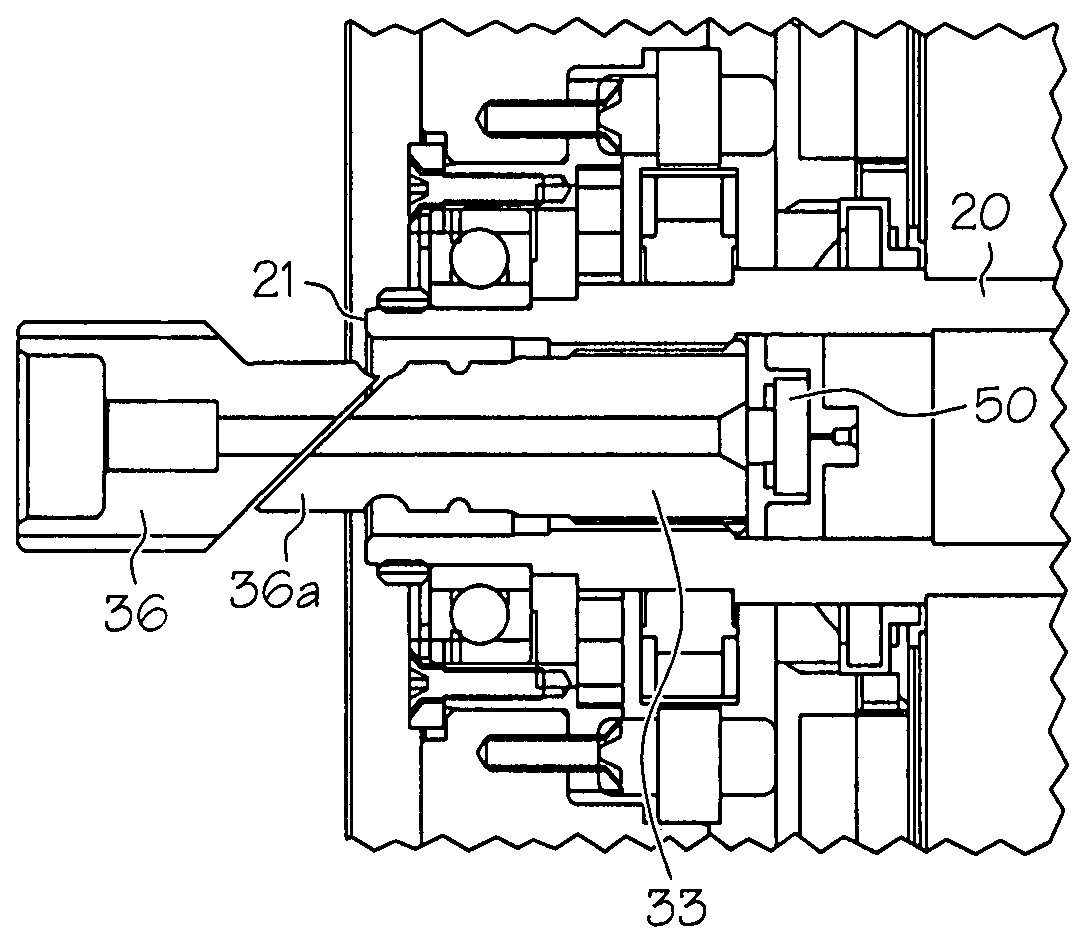
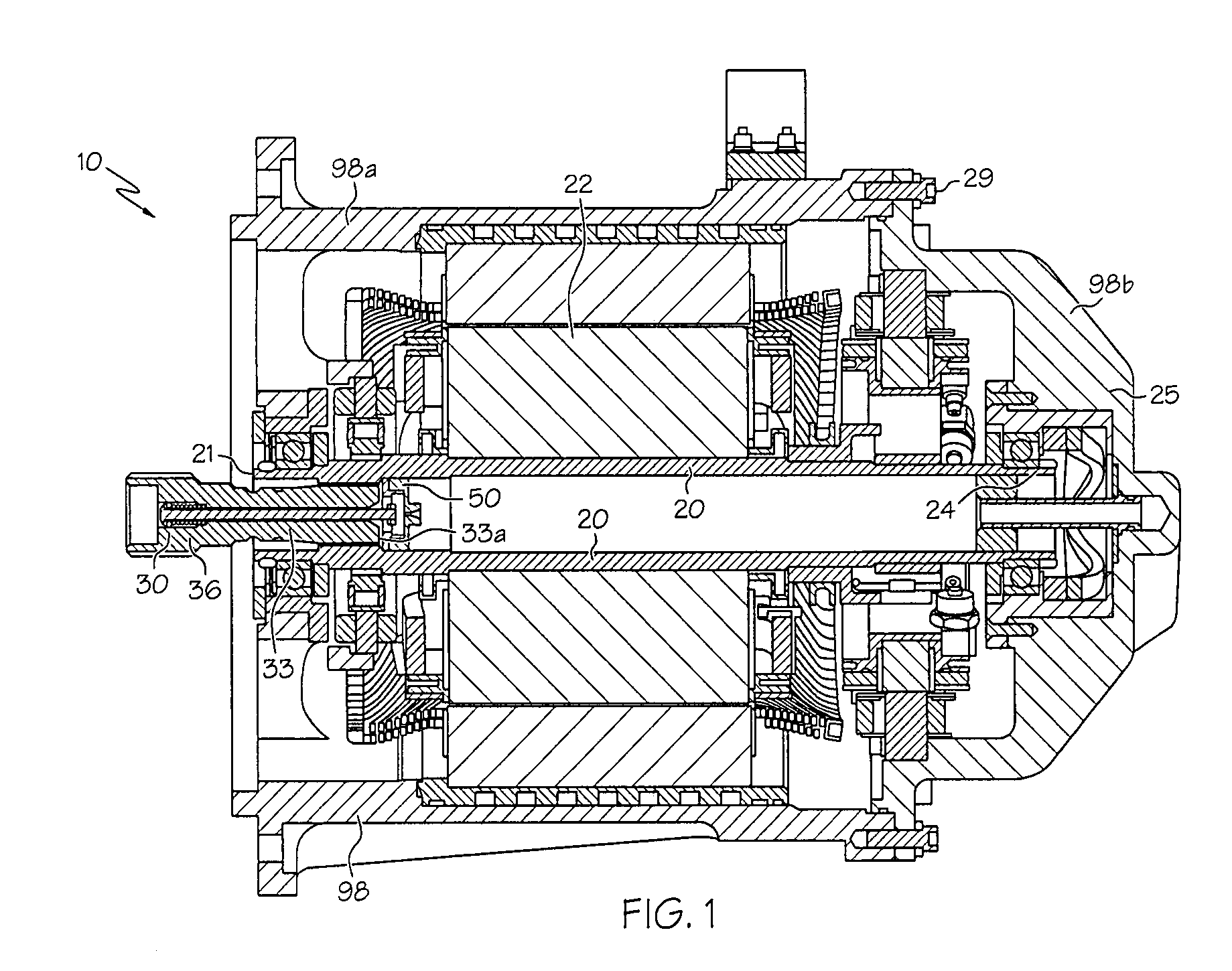
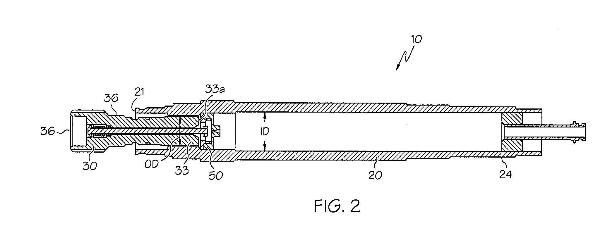
[0018]The present invention generally provides a stub shaft failure relief assembly, also called an axial impact shaft system, for a rotating machine, such as an aircraft generator, a high speed generator or a generator in a ground vehicle. Typically the main rotor shaft of the generator may be rotating and operatively engaged to the drive shaft of the gear box. As opposed to torsion failures, bending type failure of a stub shaft connected to a main rotor shaft of a rotating machine tends to cause an axial load against the main rotor shaft. The axial impact shaft system of the present invention may prevent an axial load from being transmitted to the mai...


PUM

PropertyMeasurementUnit
Massaaaaaaaaaa
Forceaaaaaaaaaa
Distanceaaaaaaaaaa

Abstract

A stub shaft of a main rotor shaft of a generator has its flange or shoulder removed from its outer portion so in the event of a bending failure of the stub shaft the resulting axial load of the stub shaft is not transmitted to the main rotor shaft. Instead of a retention plug adjacent the distal end of the inside portion of the stub shaft, a knock out plug is lightly press-fit into the main rotor shaft. In the event of a failure, the outside portion of the stub shaft enters the main rotor shaft without applying an axial load onto the main rotor shaft, moves axially and displaces the knock-out plug without exiting the main rotor shaft.

Description

BACKGROUND OF THE INVENTION[0001]The present invention generally relates to apparatus and methods for limiting damage to generators, other rotating machines and associated driving devices and prime movers such as gearboxes and engines and, more particularly, to apparatus and methods of limiting damage initiated by a bending failure of a stub shaft affixed to the main rotor shaft.[0002]Rotating machines, such as aircraft generators, often have a stub shaft which interfaces between the main rotor shaft of the generator and the prime mover gearbox. The stub shafts are coupled to the main engine or to auxiliary power units through the gear box. If the main rotor shaft is or becomes misaligned, for example from a ball bearing failure, a bending type failure of the stub shaft may occur. This means that the stub shaft breaks apart but not smoothly at a line perpendicular to a length of the stub shaft but rather the break may be along an incline such as a 45° incline.[0003]When the bending ...

Claims


Application Information

Patent Timeline
IPC IPC(8): F16D9/00H02K15/00
CPCY10T29/49012H02K7/003
Inventor SCHERZINGER, WILLIAMPEARSON, WAYNE T.WADDELL, SIMON L.
Owner HONEYWELL INT INC
Why Eureka
Try Eureka