Agitating Ball Mill

a technology of agitating ball mill and auxiliary grinding body, which is applied in the direction of grain treatment, etc., can solve the problems that the separating device cannot be stationary, and the grinding outlet cannot be prevented, so as to improve the backflow of the auxiliary grinding body

Active Publication Date: 2009-03-19
NETZSCH FEINMAHL TECH GMBH
View PDF1 Cites 19 Cited by
  • Summary
  • Abstract
  • Description
  • Claims
  • Application Information

AI Technical Summary

Benefits of technology

[0023]If the separating device is employed with a drive arranged independently from the agitating shaft it can be an advantage if the spirals are inserted between two holohedral end faces.
[0024]To improve the backflow of the auxiliary grinding bodies it can be an advantage if the end faces lo

Problems solved by technology

Because of the short distance which the auxiliary grinding bodies have to cover between the wing elements entry o

Method used


Image

  • Agitating Ball Mill
  • Agitating Ball Mill
  • Agitating Ball Mill

Examples


Embodiment Construction

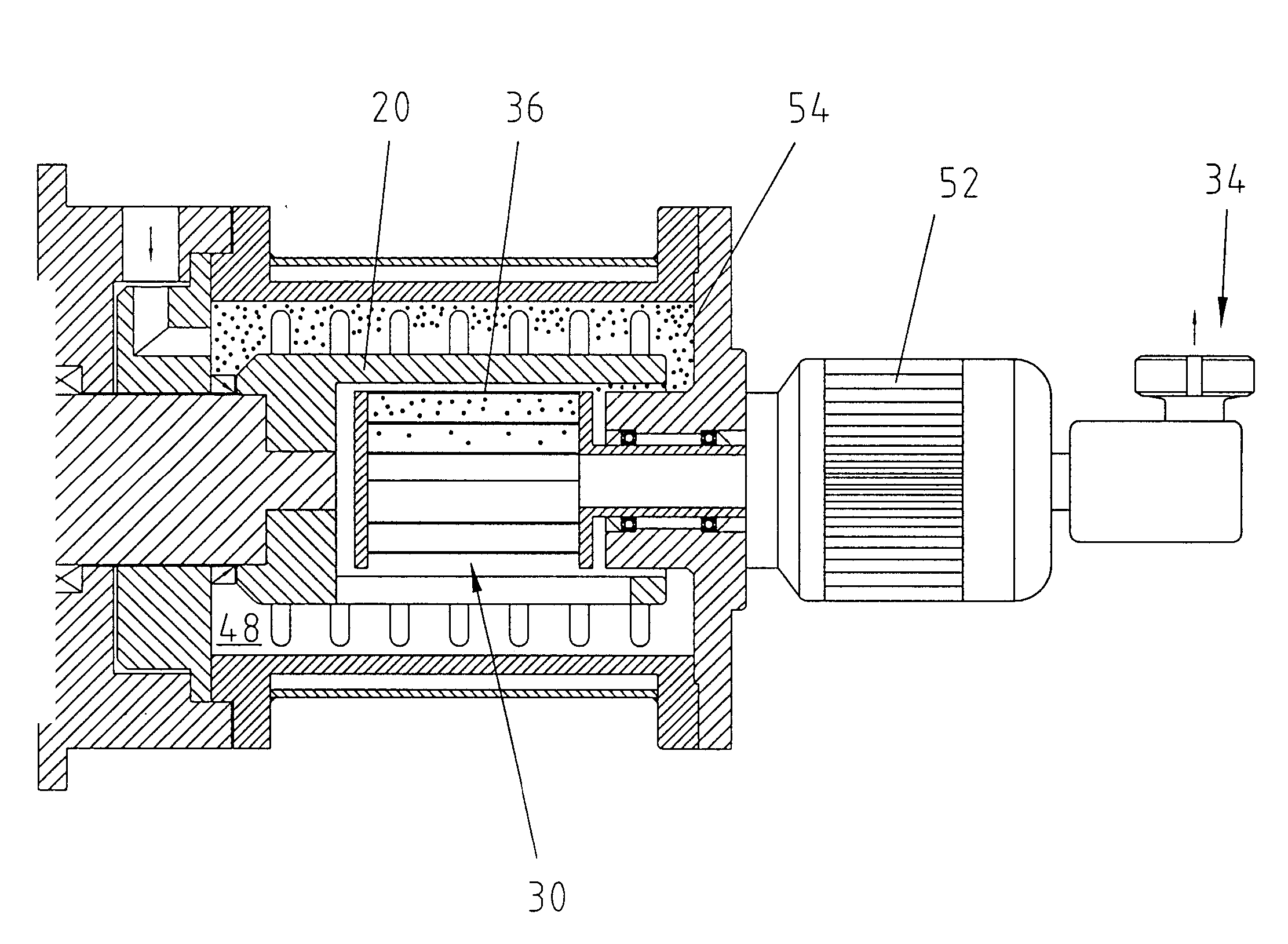
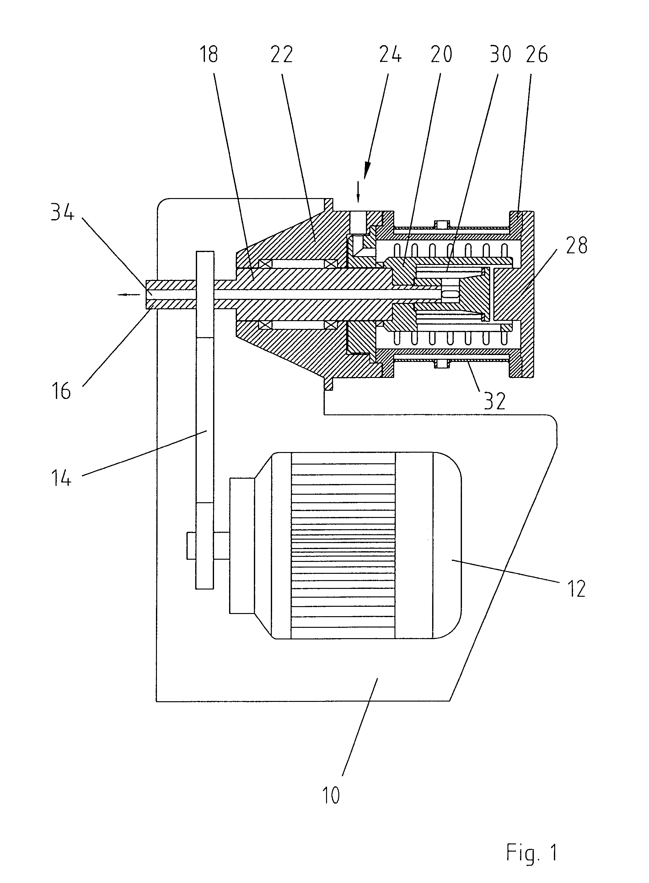
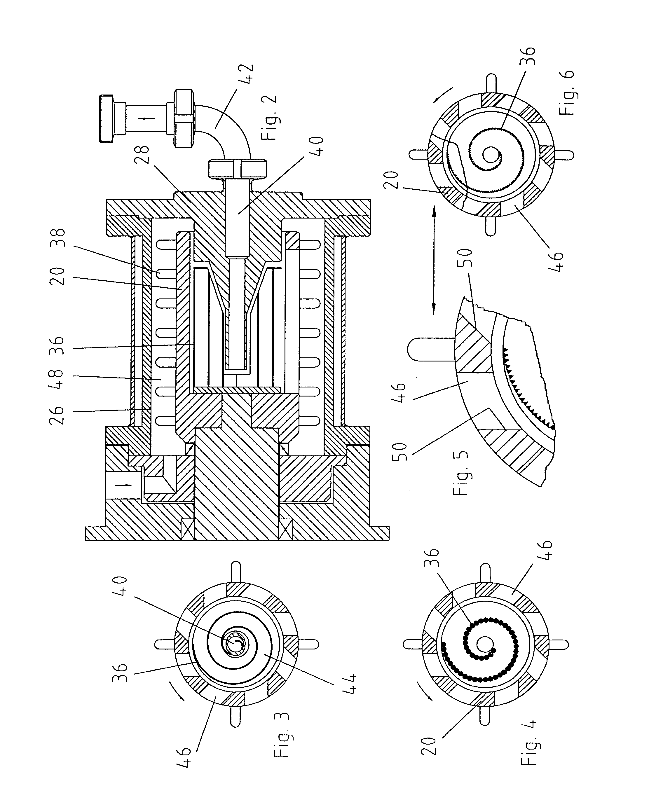
[0050]The agitating ball mill according to the invention consists of a housing 10 in which a drive 12 in form of an electric motor is seated. The drive is in connection with a drive shaft 16 by means of a drive belt 14. This drive shaft merges with the bearing shaft 18 which in turn is connected with the agitating shaft 20. On the upper side of the bearing housing 22 is located the grinding stock inlet 24. The grinding chamber 48 is limited by the grinding vessel 26 surrounding the agitating shaft 20 and the grinding vessel base 28. The separating device 30, with which the auxiliary grinding bodies 54 are separated from the grinding stock, is seated within the agitating shaft 20. To cool or heat the grinding vessel the latter is surrounded in a double-walled manner by a jacket 32 capable of being cooled and heated. The grinding stock leaves the grinding vessel via a central grinding stock outlet which leads from the agitating shaft via the bearing shaft as far as the drive shaft. FI...


PUM


Abstract

Agitating ball mill with a cylindrical grinding vessel comprising at least one grinding stock inlet and at least one grinding stock outlet wherein in the grinding vessel an agitating shaft connected with a drive is arranged which transmits a part of the drive energy to auxiliary grinding bodies which are loosely arranged in the grinding vessel and a separating device arranged in front of the grinding vessel outlet.

Description

CROSS-REFERENCE TO RELATED APPLICATIONS[0001]The present application claims priority from German patent application 10 2007 043 670.1, filed on Sep. 13, 2007, the content of which is incorporated herein by reference.FIELD OF THE INVENTION[0002]The invention relates to an agitating ball mill with a cylindrical grinding vessel having at least one grinding stock inlet and at least one grinding stock outlet, wherein in the grinding stock vessel an agitating shaft connected with a drive is arranged which transmits a part of the drive energy to auxiliary grinding bodies which are loosely arranged in the grinding vessel and a separating device arranged in front of the grinding stock outletBACKGROUND OF THE INVENTION[0003]An agitating ball mill of this kind emerges from EP 1 468 739 A1. With this horizontally arranged agitating mill the grinding vessel is in connection with a grinding stock inlet and a grinding stock outlet. In the grinding vessel proper is located an agitating shaft which ...

Claims


Application Information

Patent Timeline
IPC IPC(8): B02C17/00
CPCB02C17/161B02C17/00B02C17/16
Inventor PAUSCH, HORST
Owner NETZSCH FEINMAHL TECH GMBH
Why Eureka
Try Eureka