Operating method for a pump, in particular for a multiphase pump, and pump

a multi-phase pump and operating method technology, applied in the field of multi-phase pumps, can solve the problems of unstable operating state of multi-phase pumps, high operating pressure of pressure-elevating pumps, and extremely fluctuating flow rates, so as to avoid unstable operating states, large variations, and high cost. cost

Active Publication Date: 2016-06-23
SULZER MANAGEMENT AG
View PDF2 Cites 12 Cited by
  • Summary
  • Abstract
  • Description
  • Claims
  • Application Information

AI Technical Summary

Benefits of technology

[0009]Such effects can cause the multiphase pump to enter into an unstable operating state, which is also called a surge or surging, due to too low a flow rate. Such unstable operating states are characterized by extremely fluctuating flow rates, pressure shocks, large performance and pressure fluctuations as well as strong vibrations of the pump. Such unstable operating states represent an extremely great load on the pump itself and on the adjacent installations. If a multiphase pump is operated for too long in such an unstable operating state, this can result in premature material fatigue, much higher wear, defects, up to the failure of the complete pump, whereby disadvantageous effects on the installations provided downstream of the pump result. The failure of the multiphase pump can even lead to the total production process being interrupted, which is naturally very disadvantageous from an economic standpoint.
[0010]To remedy or at least to attenuate the problems resulting from variations in the phase distribution, it is known to provide a buffer tank upstream of the multiphase pump whose volume and inner design is adapted to the respective application. This buffer tank acts so-to-say as a filter or as an integrator and can thus absorb or damp sudden changes in the phase distribution of the fluid so that they cannot enter into the inlet of the multiphase pump or only in very weakened form.
[0011]However, since such buffer tanks cannot be designed with any desired size and since they can also not damp out all variations of the phase distribution, a security against underflow, or a surge regulator, is frequently provided with a multiphase pump. This is typically also called a surge control or surge protection and is intended to prevent the multiphase pump from entering into such an unstable operating state. It is a known measure for the surge control or regulation to provide a return line through which the fluid conveyed by the multiphase pump can be led back from the pressure side of the pump to the intake side. One or also more control valves, for example two control valves, are provided in this return line and can be controlled by the surge regulator and accordingly allow a smaller or larger flow through the return line. If, for example, two control valves are provided, one is frequently intended to compensate fluctuations in the phase distribution, while the other very quickly opens the total flow cross-section of the return line in the case of extremely large fluctuations. The logic of the surge regulator is usually integrated in the control device of the pump which is nowadays as a rule designed as a digital control system.If very high proportions of gas are present in the multiphase fluid to be pumped, then a cooling system can in particular also be provided in the return line to avoid too great a thermal load or heat build-up.
[0012]A flowmeter is furthermore provided between the opening of the return line on the intake side and the inlet of the multiphase pump.
[0013]A limit curve is typically stored in the corresponding control unit for the surge regulator. When the limit curve is reached counter-measures have to be initiated. The limit curve is fixed on the basis of a surge limit which indicates the parameter constellations at which the transition into an unstable operating state takes place. This surge limit is determined on the basis of empirical values and / or on the basis of experimentally determined data. The limit curve is then fixed at a certain “safety margin” from the surge limit to avoid unstable operating states during the operation of the pump. If the pump reaches the limit curve during operation, then the surge regulator controls the control valve or control valves such that the backflow in the return line is increased and the pump moves away from the limit curve again.
[0014]Surge regulators or securities against underflow known today require knowledge of the current (actual) flow rate, of the current (actual) phase distribution of the conveyed multiphase fluid and the current (actual) rotational speed of the pump. A direct measurement of the flow rate and of the actual phase distribution using a single instrument or sensor is, however, not possible because such measurement instruments are not available. The flowmeter must therefore be designed as a multiphase flowmeter. The multiphase flowmeter determines the flow rate on the basis of a simultaneous technical measurement of directly accessible process values such as the absolute pressure, differential pressure, density and temperature, which are then processed in a semi-empirical model to determine or estimate the actual flow rate and the actual phase distribution of the fluid in the multiphase flowmeter. Such multiphase flowmeters are very complicated, cost-intensive and complex pieces of apparatus which have some further disadvantages. The different sensors in a multiphase flowmeter for measuring the different process parameters have very large variations with respect to the update rate of the respectively determined process parameter. The sensor with the smallest update rate then naturally determines the maximum possible update rate of the multiphase flowmeter. This maximum update rate is sometimes not sufficient to ensure a reliable surge control or a reliable security against underflow. For sub-sea installations and the associated maritime environment in particular, the corresponding pieces of apparatus have even smaller update rates, which further reduces the dynamic performance capability of the surge regulator. Since greater safety margins from the limit curve are thus necessary to avoid unstable operating states, the operating range of the multiphase pump is further restricted.

Problems solved by technology

These pressure-elevating pumps frequently have to generate high pressures because the boreholes are very deep or are difficult to access so that very long lines or pipelines are required between the borehole and the processing or storage devices.
Such effects can cause the multiphase pump to enter into an unstable operating state, which is also called a surge or surging, due to too low a flow rate.
Such unstable operating states are characterized by extremely fluctuating flow rates, pressure shocks, large performance and pressure fluctuations as well as strong vibrations of the pump.
Such unstable operating states represent an extremely great load on the pump itself and on the adjacent installations.
If a multiphase pump is operated for too long in such an unstable operating state, this can result in premature material fatigue, much higher wear, defects, up to the failure of the complete pump, whereby disadvantageous effects on the installations provided downstream of the pump result.
The failure of the multiphase pump can even lead to the total production process being interrupted, which is naturally very disadvantageous from an economic standpoint.
However, since such buffer tanks cannot be designed with any desired size and since they can also not damp out all variations of the phase distribution, a security against underflow, or a surge regulator, is frequently provided with a multiphase pump.
A direct measurement of the flow rate and of the actual phase distribution using a single instrument or sensor is, however, not possible because such measurement instruments are not available.
Such multiphase flowmeters are very complicated, cost-intensive and complex pieces of apparatus which have some further disadvantages.
For sub-sea installations and the associated maritime environment in particular, the corresponding pieces of apparatus have even smaller update rates, which further reduces the dynamic performance capability of the surge regulator.
Since greater safety margins from the limit curve are thus necessary to avoid unstable operating states, the operating range of the multiphase pump is further restricted.
In addition, these complex multiphase flowmeters require substantial space for their installation which is often not available, for example on platforms, FPSOs or in a sub-sea arrangement on the seabed.
The installation of a multiphase flowmeter directly upstream of the inlet of the pump is, however, often not possible at all, for example for space reasons.
Similar problems can also occur with single-phase pumps, that is with pumps which serve for the conveying of a single-phase fluid, for example a liquid.
Similar problems as described further above also result with these flowmeters, namely they can in particular frequently not be positioned at the desired point, or only with a great effort, and their update rates are frequently too small or the delays in the signal transmission are too large so that the surge regulator has to be designed with very large safety margins.
The operating range in which the pump can be safely operated is thereby restricted.

Method used


Image

  • Operating method for a pump, in particular for a multiphase pump, and pump
  • Operating method for a pump, in particular for a multiphase pump, and pump
  • Operating method for a pump, in particular for a multiphase pump, and pump

Examples


Embodiment Construction

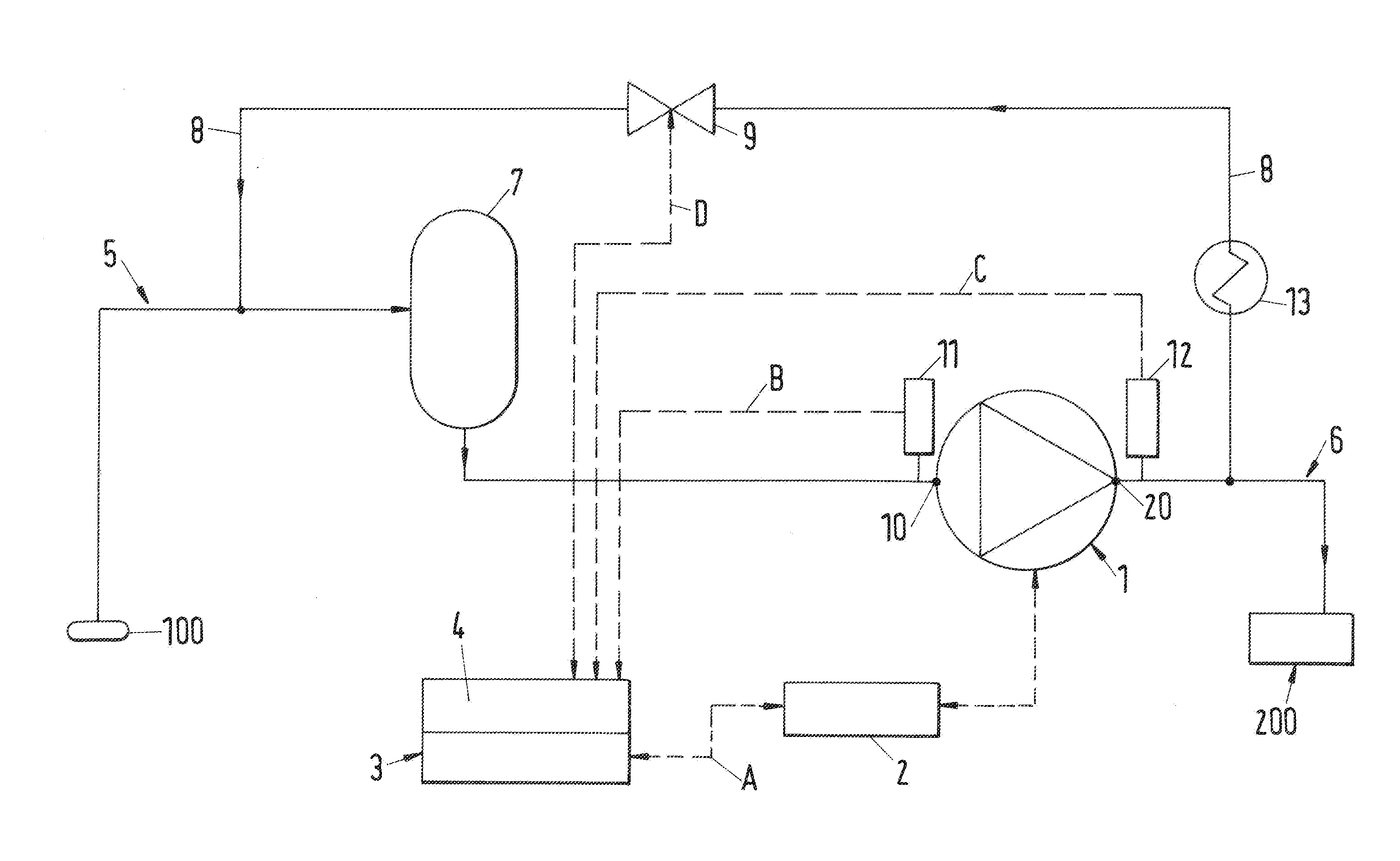
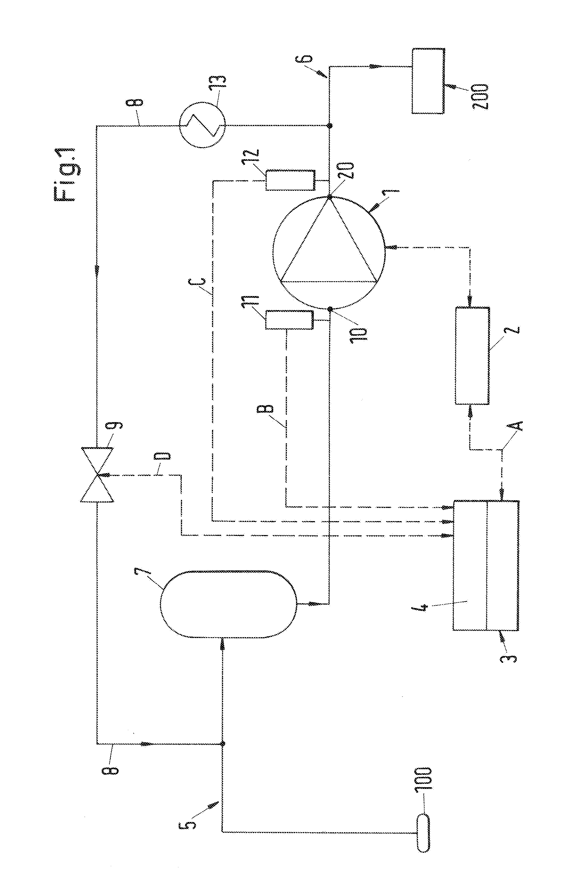
[0044]FIG. 1 illustrates in a schematic representation an embodiment of the invention in both an apparatus respect and a technical method respect. In the following, an embodiment of the operating method in accordance with the invention and an embodiment of a pump in accordance with the invention, which is designated as a whole by the reference numeral 1, will be explained with reference to FIG. 1. The pump is configured as a multiphase pump. In this respect, reference is made with an exemplary character to the application important in practice that the multiphase pump 1 is configured as a centrifugal pump and as a pressure-elevating pump which is also typically called a booster pump. In this application, the multiphase pump is used for oil production and gas production and in particular for sub-sea oil production and gas production in which the outlet of a borehole 100 is located on the seabed from where the petroleum and the natural gas are conveyed to a storage and processing appa...


PUM


Abstract

An operating method for a pump includes providing a return line for returning the fluid from a high-pressure side to a low-pressure side, controlling a control valve in the return line with a surge control unit for avoiding an unstable operating state, the control valve controlling the throughflow through the return line, storing a limit curve for a control parameter in the surge control unit, comparing an actual value of the control parameter with the limit curve during the operation of the pump; and when the actual value of the control parameter reaches the limit curve, controlling the control valve in the return line such that the actual value of the control parameter is moved away from the limit curve, an operating parameter of the pump being used as the control parameter.

Description

CROSS-REFERENCE TO RELATED APPLICATIONS[0001]This application claims priority to EP Application No. 14198870.9, filed Dec. 18, 2014, the contents of which is hereby incorporated herein by reference.BACKGROUND[0002]1. Field of the Invention[0003]The invention relates to an operating method for a pump, in particular a multiphase pump, and to a pump, in particular a multiphase pump, for conveying a fluid in accordance with the preamble of the independent claim of the respective category.[0004]2. Background of the Invention[0005]Multiphase pumps are pumps with which fluids can be conveyed which comprise a mixture of a plurality of phases, for example a liquid phase and a gaseous phase. Such pumps have been well known for a long time and are produced in a large number of embodiments, frequently as centrifugal pumps, for example as single-suction pumps or as double-suction pumps and as single-stage or multi-stage pumps. The field of application of these pumps is very wide; they are used, ...

Claims


Application Information

Patent Timeline
Patent Type & Authority Applications(United States)
IPC IPC(8): F04D27/02F04D17/08F04D29/22F04D31/00F04D29/42F04D29/28F04D1/00F04D15/00
CPCF04D27/02F04D1/00F04D17/08F04D15/0022F04D29/22F04D29/4206F04D29/426F04D29/28F04D31/00F04D15/02F05D2270/30F05D2270/3015F05D2270/335F04D27/001F04D27/0223F04D15/0011F04D15/0088F04D13/10F04D29/668
Inventor SCHNEIDER, LORENZ
Owner SULZER MANAGEMENT AG
Why Eureka
Try Eureka