Control system for a linear vibration motor

A technology of linear vibration and motor drive, applied in the control system, AC motor control, control/regulation system, etc., can solve the problems of increased copper loss or core loss of motor efficiency, reduced motor efficiency, increased current, etc., to achieve stability and accuracy The effect of stroke control

Inactive Publication Date: 2004-11-10
PANASONIC CORP
View PDF1 Cites 13 Cited by
  • Summary
  • Abstract
  • Description
  • Claims
  • Application Information

AI Technical Summary

Problems solved by technology

[0019] Accordingly, in the conventional linear vibration motor, the number of windings of the coil, which is the stator of the linear vibration motor, is determined based on the maximum output obtained, resulting in a possibility of lower motor efficiency in the output region of the highest frequency of use. parts
[0020] For example, when reducing the number of windings of the motor coil to increase the maximum output of the linear vibration motor, the amount of current increases in the output region of the highest frequency of use, that is, in the output region where the motor output power is low, which causes the motor efficiency to vary depending on the motor The copper loss or core loss in the increase, or the converter loss increases and decreases

Method used


Image

  • Control system for a linear vibration motor
  • Control system for a linear vibration motor
  • Control system for a linear vibration motor

Examples


Embodiment 1

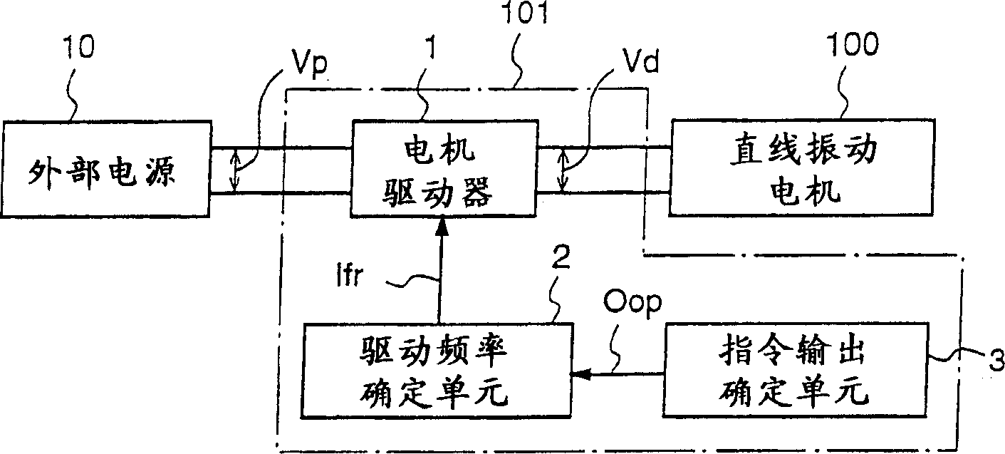
[0057] figure 1 is a block diagram for explaining the motor drive device according to the first embodiment of the present invention.

[0058] The motor driving device 101 according to the first embodiment drives the linear vibration motor 100 having a stator, a mover, and a support mover to form a spring vibration system including the mover at a drive frequency according to a desired motor output the support spring. The stator includes an electromagnet obtained by winding an iron core with a coil, and the mover includes a permanent magnet.

[0059] More specifically, the motor drive device 101 includes a command output determining unit 3 for determining a target output that is a motor output required by the linear vibration motor 100 and outputting an output command signal Oop indicating the determined target output.

[0060] Further, the motor drive device 101 includes: a drive frequency determination unit 2, which determines the drive frequency of the linear vibration moto...

Embodiment 2

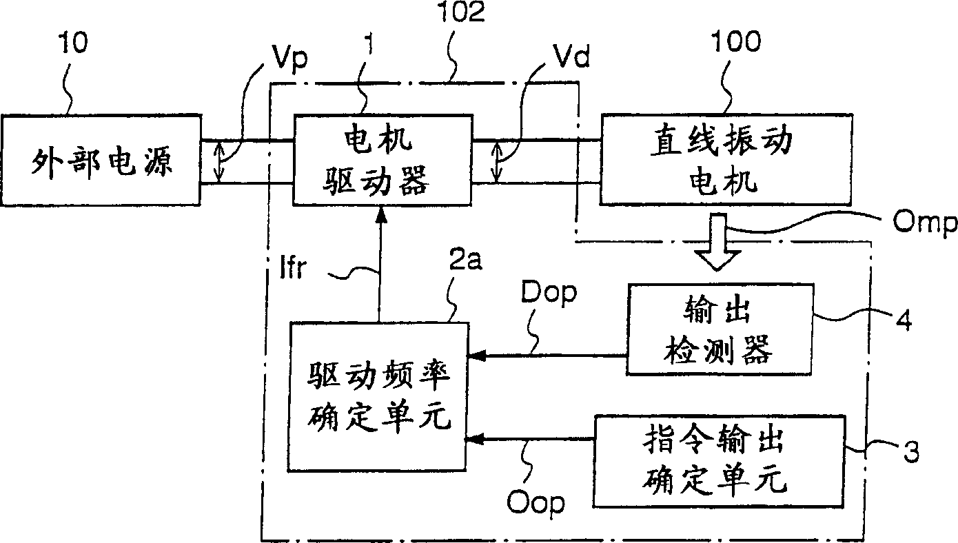
[0078] figure 2 is a block diagram for explaining a motor drive device according to a second embodiment of the present invention.

[0079] According to the motor driving device 102 of the second embodiment, the linear vibration motor 100 is driven, and the drive frequency is adjusted to reduce the difference between the motor output and the desired motor output, wherein the linear vibration motor 100 has a stator, a mover, and a support mover to A support spring forming a spring vibration system including the mover. The linear vibration motor 100 according to this second embodiment is exactly the same as that of the first embodiment.

[0080] More specifically, the motor drive device 102 includes: a command output determining unit 3, which is used to determine the target output and output an output command signal Oop indicating the determined target output, wherein the target output is the motor output required by the linear vibration motor 100 and, an output detector 4, wh...

Embodiment 3

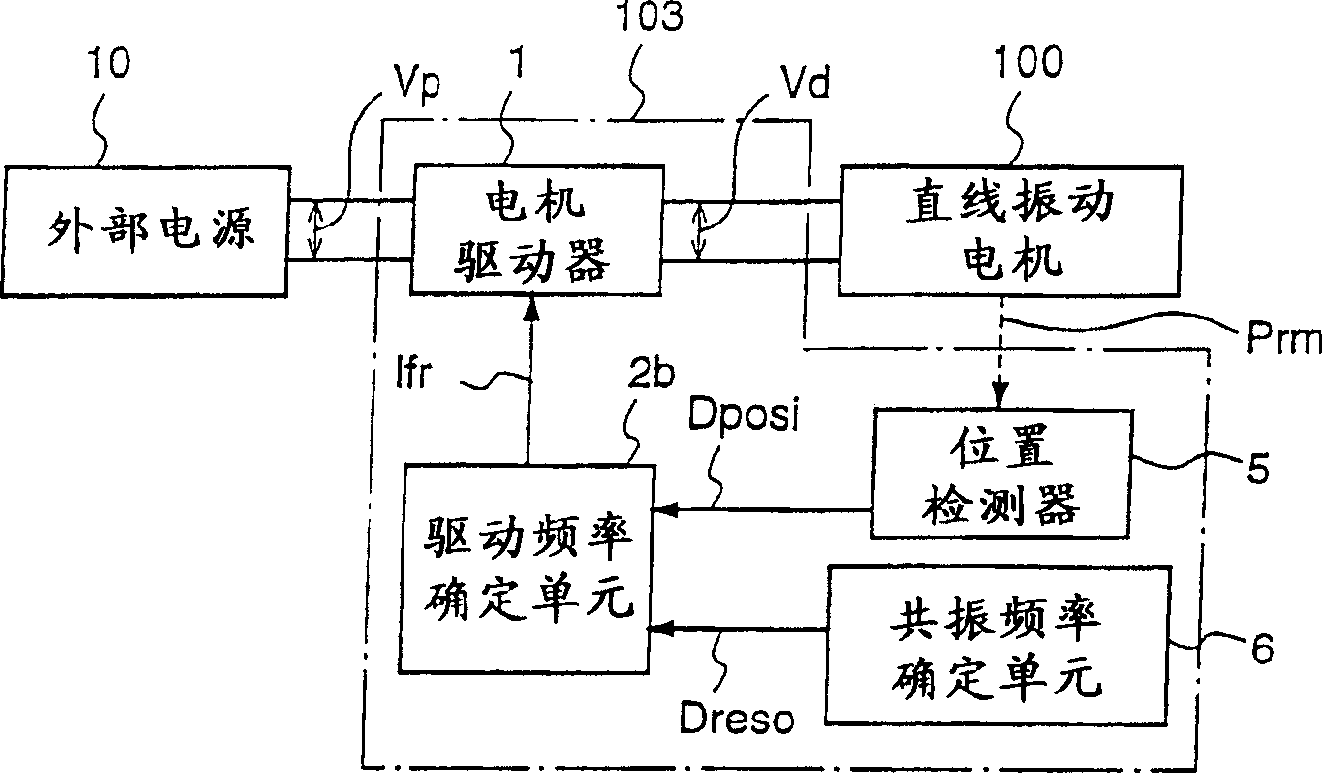
[0099] FIG. 3(a) is a block diagram for explaining a motor driving device according to a third embodiment of the present invention.

[0100] The motor driving device 103 according to the third embodiment drives the linear vibration motor 100 having a stator, a mover, and a support mover to form a spring vibration including the mover at a drive frequency determined based on the position of the mover System support springs. The linear vibration motor 100 of this third embodiment is exactly the same as that of the first embodiment.

[0101] Specifically, the motor drive device 103 includes: a position detector 5, which is used to detect the position of the reciprocating mover and output a position detection signal Dposi indicating the position of the detected mover; a resonance frequency determination unit 6, which is used for output a resonance frequency signal Dreso indicating the resonance frequency of the linear vibration motor 100; a drive frequency determination unit 2b th...


PUM


Abstract

A motor driving apparatus (101) for driving a linear vibration motor (100) is privided with an order output determining unit (3) for determining a motor output required of the linear vibration motor (100), and a driving frequency determining unit (2) for determining a driving frequency of the linear vibration motor (100) on the basis of the determined motor output, and an amplitude-fixed AC voltage (Vd) having a frequency equal to the determined driving frequency is applied to the linear vibration motor (100), whereby the output of the linear vibration motor (100) can be controlled without changing the amplitude value of the driving voltage applied to the linear vibration motor (100).

Description

technical field [0001] The present invention relates to a motor driving device, and more particularly to a motor driving device for driving a linear vibration motor having a mover and a spring member supporting the mover. Background technique [0002] Conventional devices using linear vibration motors include vibration generators that notify incoming calls through mechanical vibrations, such as cell phones, compressors for compressing and circulating gas or fluid, and reciprocating electric shavers. Compressors and electric shavers use linear vibrating motors as their drive sources. [0003] A typical linear vibration motor has the structure of a single-phase synchronous motor, that is, it has a mover including permanent magnets and a stator obtained by winding a coil on an iron core, and the mover reciprocates when AC voltage is applied to the coil. [0004] As described above, when vibration is generated by the reciprocating motion of the mover, a large electromagnetic fo...

Claims


Application Information

Patent Timeline
Patent Type & Authority Applications(China)
IPC IPC(8): B26B19/28B26B19/38F24H4/00F25B1/02F25B13/00H02K33/16H02P25/02
CPCF25B13/00F24H4/00B26B19/282B26B19/388H02P25/027H02K33/16F25B2400/073B26B19/38F25B1/02H02P25/032H02P25/00G05D19/02
Inventor 植田光男中田秀树吉田诚
Owner PANASONIC CORP
Why Eureka
Try Eureka