Sealing arrangement

a technology of sealing arrangement and sealing liquid, applied in the direction of engine seals, engine components, mechanical apparatus, etc., can solve the problems of low wear and tear, and achieve the effect of enhancing the backflow of hydraulic liquid, and preventing premature exertion of pressur

Active Publication Date: 2014-03-25
TRELLEBORG SEALING SOLUTIONS GERMANY
View PDF9 Cites 1 Cited by
  • Summary
  • Abstract
  • Description
  • Claims
  • Application Information

AI Technical Summary

Benefits of technology

[0010]The spatial configuration and alignment of the recesses in the inner surface of the U-Cup according to the invention improves backflow of hydraulic liquid from the low-pressure side of the U-cup to the high-pressure side of the U-cup across the inner sealing lip and thereby reduces the overall leakage rate
[0020]Finally, in an advantageous embodiment, the U-cup has an inner surface facing the movable machine part, and the inner surface has microstructures, in particular spherical calottes. This improves the capacity of dragging back hydraulic oil and prevents flat abutment of the U-cup and the movable machine part.

Problems solved by technology

However, more hydraulic fluid than necessary for an efficient seal as well as low wear of the U-cup adheres to the movable machine part and is dragged from the high-pressure side to the low-pressure side of the U-cup (beyond the inner sealing lip).

Method used


Image

  • Sealing arrangement
  • Sealing arrangement
  • Sealing arrangement

Examples


Embodiment Construction

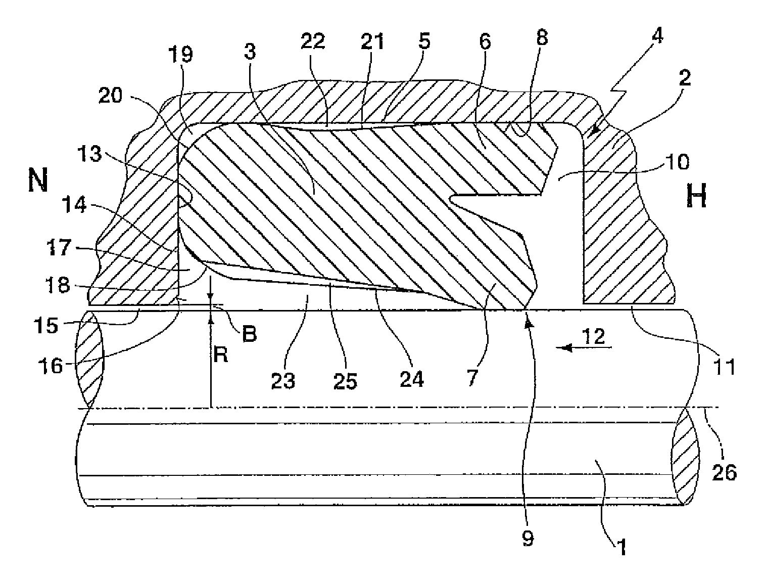
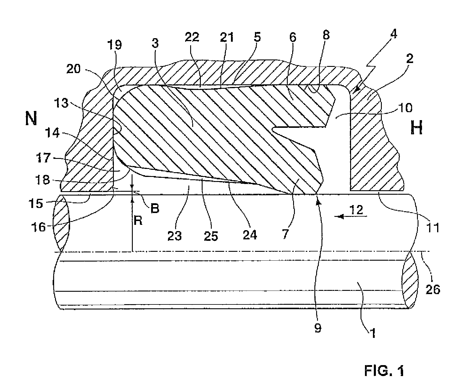
[0025]FIG. 1 shows a cross-section of an embodiment of an inventive sealing arrangement in the unpressurized (i.e. largely undeformed) state, comprising a movable machine part 1 which is herein formed as cylindrical piston rod, a stationary machine part 2 and a U-cup 3. The U-cup 3 is associated with an axis 26 with respect to which the U-cup 3 is approximately rotationally symmetrical. The axis 26 coincides with the cylindrical axis of the movable machine part 1. The stationary machine component 2 has a profiled section which is formed as groove 4 having a square cross-section. The U-cup 3 is disposed in the groove 4, wherein, due to radial prestress, i.e. pressure of the U-cup 3 against a groove bottom 5, a sliding motion of the U-cup 3 in the groove 4 is eliminated due to frictional adhesion. The U-cup 3 is formed from a viscoplastic synthetic material, such as polyurethane. On the high-pressure side (high-pressure side H, on the right hand side in the figure) the U-cup 3 has a r...


PUM


Abstract

In a U-cup based seal of a rod, the basic body of the U-cup 3 is recessed relative to a square cross-sectional shape in the region of a radially inner outer edge 18 on the low pressure side in order to obtain a space 17 between the U-cup 3 and the opening, i.e. the passage opening 16 of a sealing gap 15, leading into a rectangular groove 4 guiding the U-cup 3. This space 17 remains at least partially also upon pressurization such that the U-cup 3 complete remains in the groove 4 upon pressurization and is not extruded into the sealing gap 15. This considerably reduces wear of the U-cup 3. An inner surface 24 of the U-cup shows liquid dragging bore reliefs formed as recesses 25 in the inner surface 24 of the U-cup 3 for transferring hydraulic liquid, disposed on a surface of the translatory movable machine part 1, from a low-pressure side N of the U-cup to a high-pressure side H of the U-cup 3 upon translatory movement of the movable machine part 1. The recesses 25 each extend in an axial direction from the low pressure side N of the U-cup towards the inner sealing lip 7 and each recess is radially confined by side walls 26 which converge in the direction of the inner sealing lip such as to form an imaginary intersection located beyond the inner sealing lip 7 on the high-pressure side of the U-cup 3.

Description

[0001]The present application is a continuation-in-part of U.S. Ser. No. 10 / 551,006 filed Sep. 27, 2005.BACKGROUND OF THE INVENTION[0002]The invention concerns a sealing arrangement comprising a U-cup of a viscoplastic synthetic material, a stationary machine part, and a translatory movable machine part with an outer radius R, wherein the U-cup is disposed as a contracting joint under radial prestress between the stationary machine part and the movable machine part in a profiled section of and / or the stationary machine part, wherein the U-cup has a radially outer and a radially inner sealing lip on a high-pressure side, wherein the stationary and the movable machine parts are separated on a low-pressure side by a sealing gap width B, wherein an abutment surface of the U-cup abuts a radially oriented region of the profiled section on the low-pressure side, wherein the U-cup has an inner radius and an outer radius, wherein both in the unpressurized state and in the pressurized state, ...

Claims


Application Information

Patent Timeline
Patent Type & Authority Patents(United States)
IPC IPC(8): F16J15/32
CPCF16J15/3236F16J15/164F16J15/56
Inventor PETER, JOERGADOLF, JEAN-JACQUESJORDAN, HOLGER
Owner TRELLEBORG SEALING SOLUTIONS GERMANY
Why Eureka
Try Eureka