
RFID system

a technology of rfid system and rfid data, which is applied in the direction of burglar alarm mechanical actuation, burglar alarm by hand-portable article removal, instruments, etc., can solve the problems of increased expenditure, less flexible settled system, and inability to obtain commercial goods data from commercial goods shelves, etc., to achieve simple and flexible communication paths

Inactive Publication Date: 2009-03-19
IBM CORP
View PDF4 Cites 14 Cited by
  • Summary
  • Abstract
  • Description
  • Claims
  • Application Information

AI Technical Summary

Benefits of technology

[0006]The present invention manages as many articles (items) as possible by using as few readers / writers as possible in the RFID system. Many articles (items) are managed by using general purpose readers / writers or different types of readers / writers in the RFID system. The present invention provides an RFID system with relatively simple and flexible communication paths between the readers / writers and a central control unit.

Problems solved by technology

As a reader / writer is relatively expensive, the expenditure for them is increased.
Further, once a great number of the sets are settled, commercial goods data cannot be obtained from the commercial goods shelves by using other types of generally used reader / writer, because an antenna selector is always connected with a reader / writer.
In other words, the settled system is less flexible.
As the number of readers / writers increases, communication lines (wiring) between the readers / writers and the central control unit (host computer) become more complicated, increasing the expenditure for the wiring.

Method used


Image

  • RFID system
  • RFID system
  • RFID system

Examples


Embodiment Construction

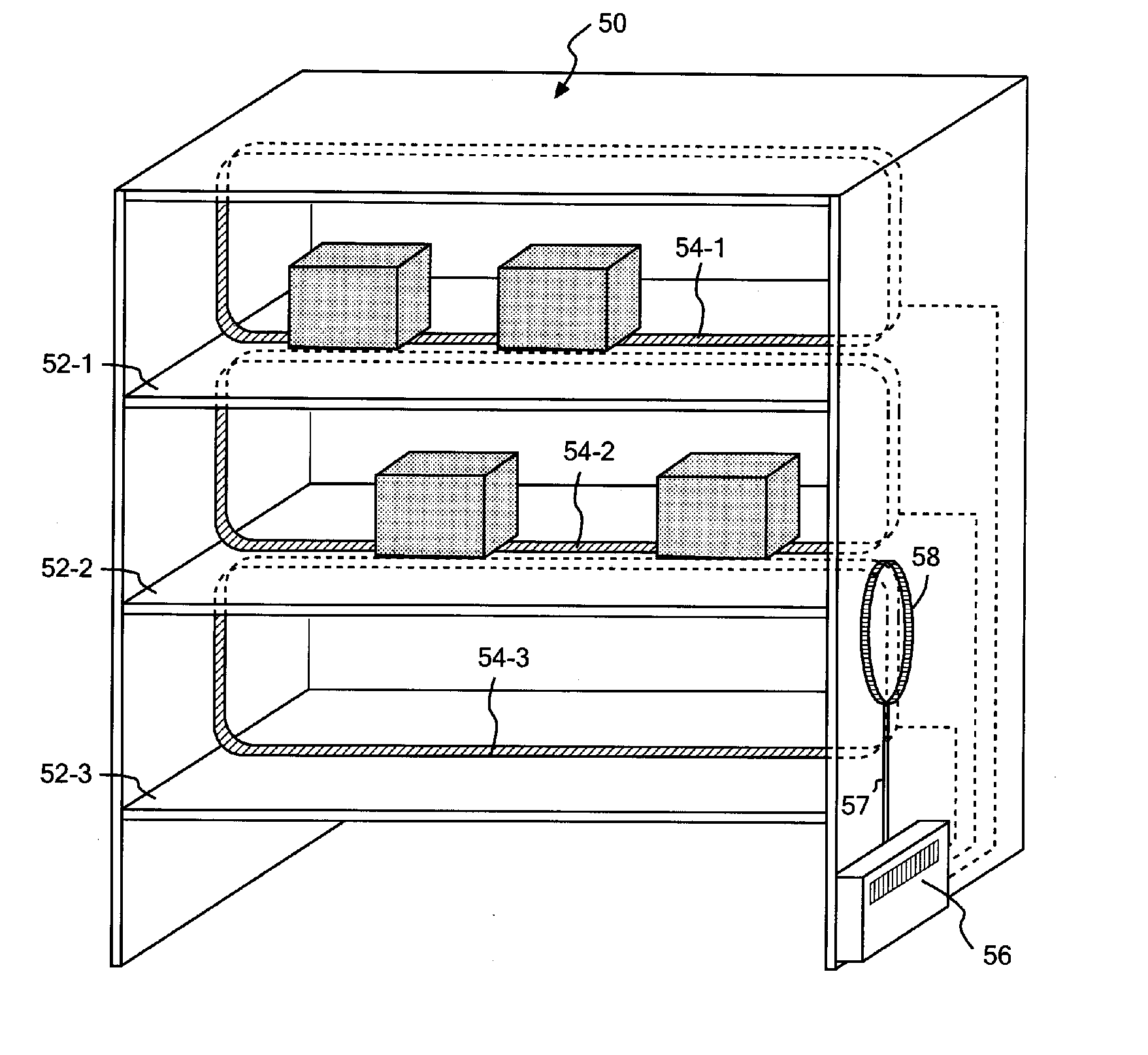
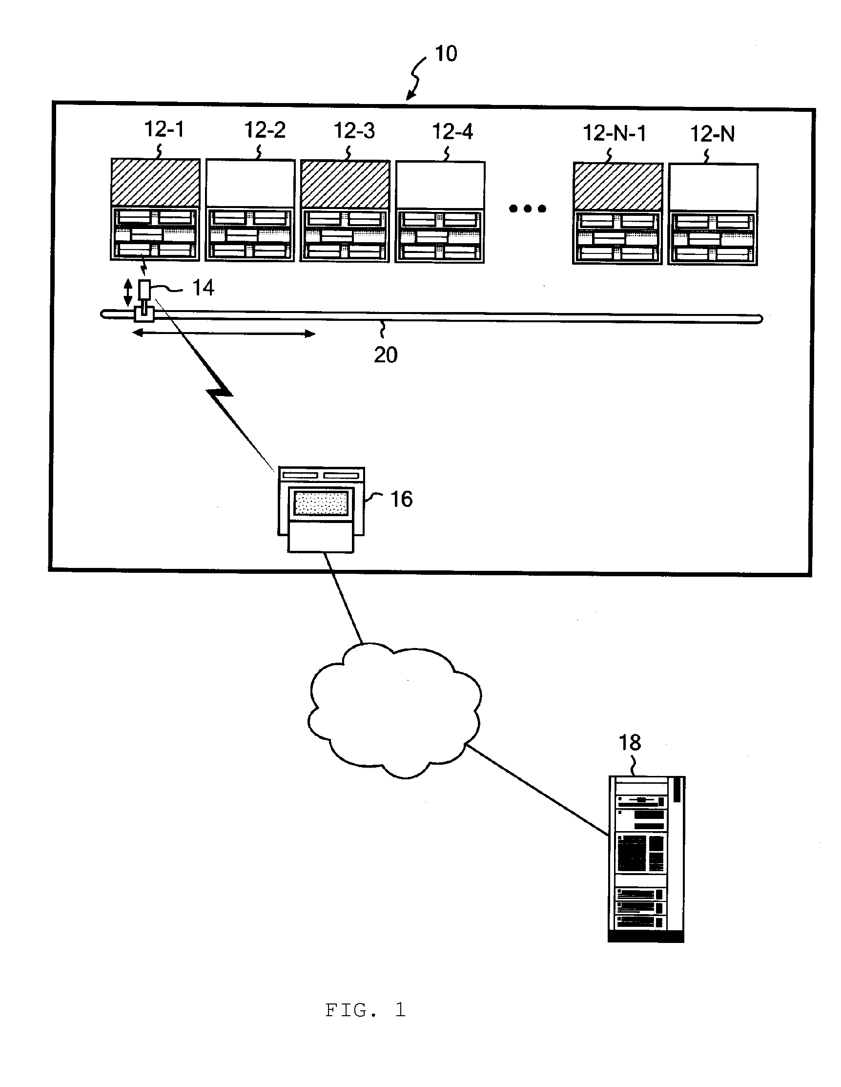
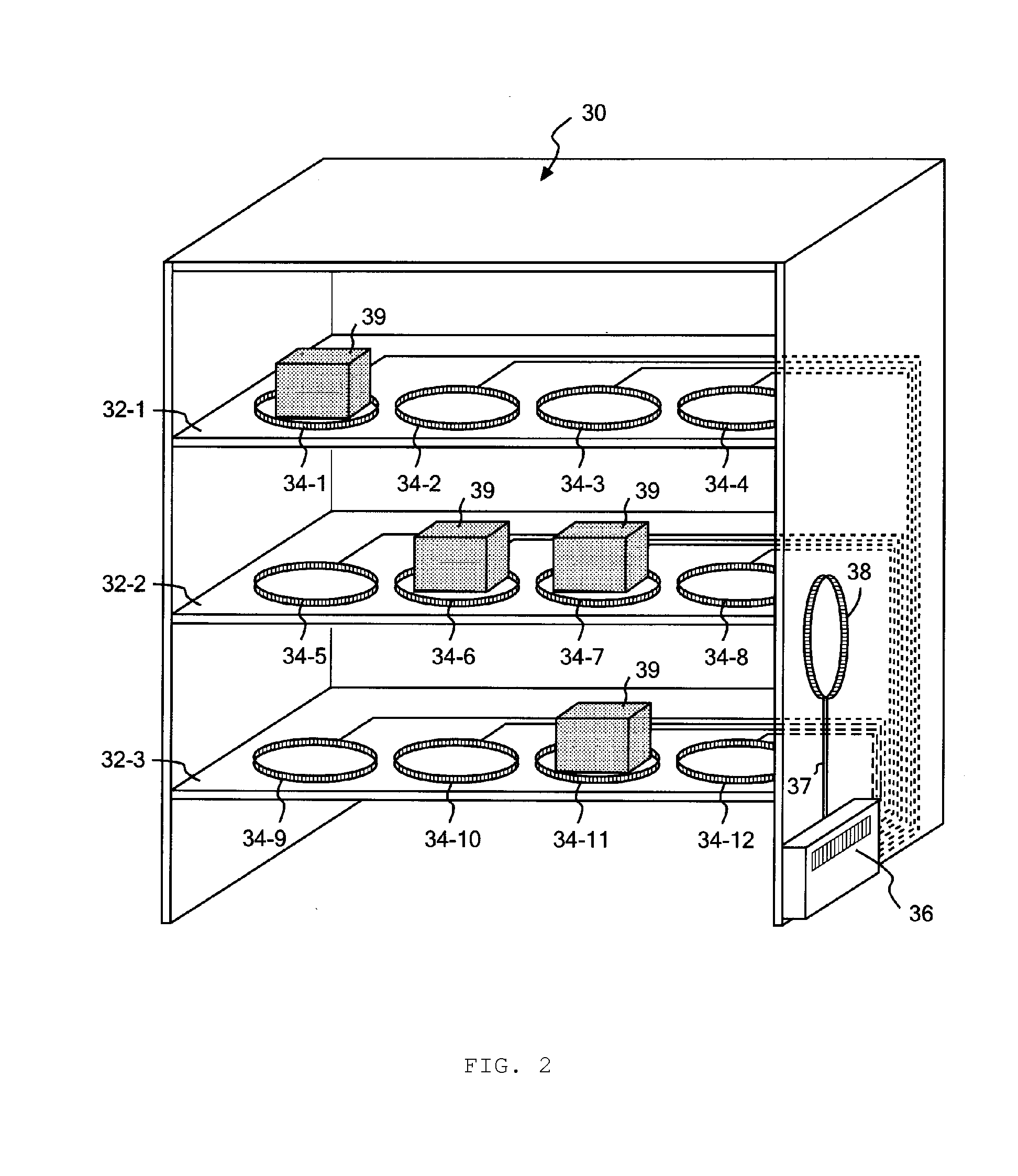
[0014]FIG. 1 is a diagram illustrating an entire RFID system according to the present invention. In FIG. 1, an item management system is provided using an RFID system. A warehouse 10 includes two or more cabinets 12-1 to 12-N therein. Each cabinet 12 may comprise a simple style cabinet such as a shelf, a closed type cabinet that can be locked, or other various types of cabinets. A plurality of the cabinets 12 include an RFID antenna according to the present invention. The cabinets 12 including an RFID antenna may comprise any of two or more cabinets 12 in a particular region of the warehouse 10, two or more cabinets 12 arranged with a predetermined space therebetween, or all of the cabinets 12. The item may be any individual object to be managed such as products or parts which are being manufactured in a factory, drugs being used in a hospital, and waste to be processed as well as commercial goods which are sold through a distribution channel.

[0015]An RFID reader / writer 14 communica...


PUM


Abstract

An RFID system according to the present invention includes an RFID antenna system including: a first antenna that can communicate with an external reader / writer; an antenna selector for connecting with the first antenna; and a plurality of second antennas that can connect with the first antenna in order via the antenna selector, each of the second antennas can communicate with an IC tag that is attached to an article placed in a region defined by the second antenna.

Description

FIELD OF THE INVENTION[0001]The present invention relates to a contactless identifying technique using an electromagnetic wave, which is generally called an RFID (Radio Frequency Identification). The present invention particularly relates to a system that uses an RFID.BACKGROUND ART[0002]RFID is a technology for sending an electromagnetic wave from an interrogator (reader / writer) to an ID (IC) tag that is attached to an object to be identified, and reading or writing the ID information on the object to be identified in a contactless manner. RFID has been widely used in management and the like on inventory or history (traceability) of items, such as commercial goods, as an RFID system with integrated circuit (IC) tags attached to the items.[0003]An RFID system includes an IC tag including an IC chip with a small antenna and a reader / writer for wirelessly communicating with the IC tag. The reader / writer has an antenna. The reader / writer sends power for driving the IC chip in the IC ta...

Claims


Application Information

Patent Timeline
IPC IPC(8): H04Q5/22H01Q21/00
CPCH01Q1/2216H04Q2213/13095H01Q7/00
Inventor FUKUDA, KAORUKIMURA, YOSHINORIMATSUEDA, TSUYOSHINISHINO, HITOSHISAKAMOTO, SHIROH
Owner IBM CORP
Learn More