Cable puller with pivot adjuster for converting between upward and downward cable pulling

a cable puller and adjuster technology, applied in the field of cable pullers, can solve the problems of difficult inverting large cable pullers, time-consuming and burdensome techniques, and the user's inability to move heavy components until, and achieve the effect of convenient conversion

Active Publication Date: 2009-03-26
GREENLEE TEXTRON
View PDF10 Cites 30 Cited by
  • Summary
  • Abstract
  • Description
  • Claims
  • Application Information

AI Technical Summary

Benefits of technology

[0009]Briefly, the present invention discloses a cable puller which can be easily converted between upward pulling and downward pulling positions. The cable puller includes an attachment system removably attached proximate a front end of the boom, a puller head moveably attached to a rear end of the boom, and a base attached to the puller head and the boom to support the cable puller.

Problems solved by technology

Although this technique works, it has the considerable drawback that the user has to move heavy components until they are upside down.
This technique can be extremely time consuming and burdensome.
It is particularly difficult to invert large cable pullers which are used to exert forces in the range of thousands of pounds.
To begin, it requires the addition of an extra part thereby increasing the cost of the cable puller.
In addition, the interaction between the rope or cable and the additional pulley or sheave creates extra drag and friction which makes pulling the cable more difficult.
Another disadvantage provided by the addition of another pulley or sheave is that extra time is needed to feed the pulling rope around the additional pulley or sheave.
Finally, use of an extra pulley or sheave introduces an extra step to the cable puller, complicating use of the device and providing another opportunity for user error.
This technique, however, also suffers from the cost and time consumption disadvantages discussed for the previous techniques.

Method used


Image

  • Cable puller with pivot adjuster for converting between upward and downward cable pulling
  • Cable puller with pivot adjuster for converting between upward and downward cable pulling
  • Cable puller with pivot adjuster for converting between upward and downward cable pulling

Examples


Embodiment Construction

[0021]While the invention may be susceptible to embodiment in different forms, there is shown in the drawings, and herein will be described in detail, a specific embodiment with the understanding that the present disclosure is to be considered an exemplification of the principles of the invention, and is not intended to limit the invention to that as illustrated and described herein.

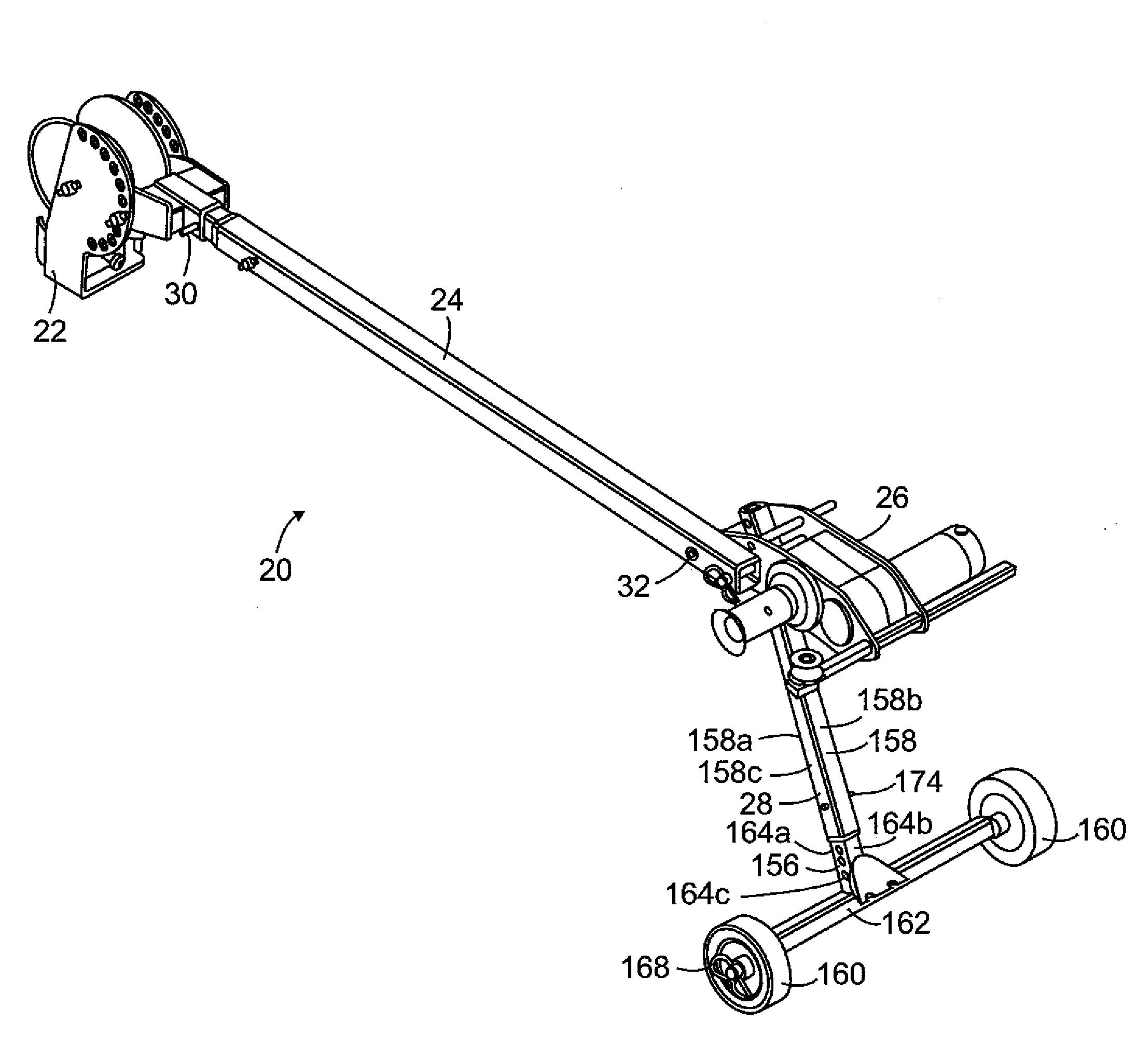
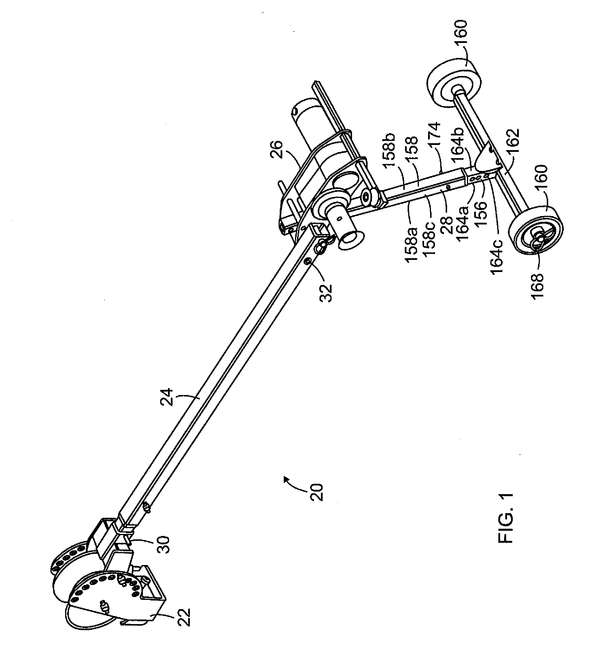
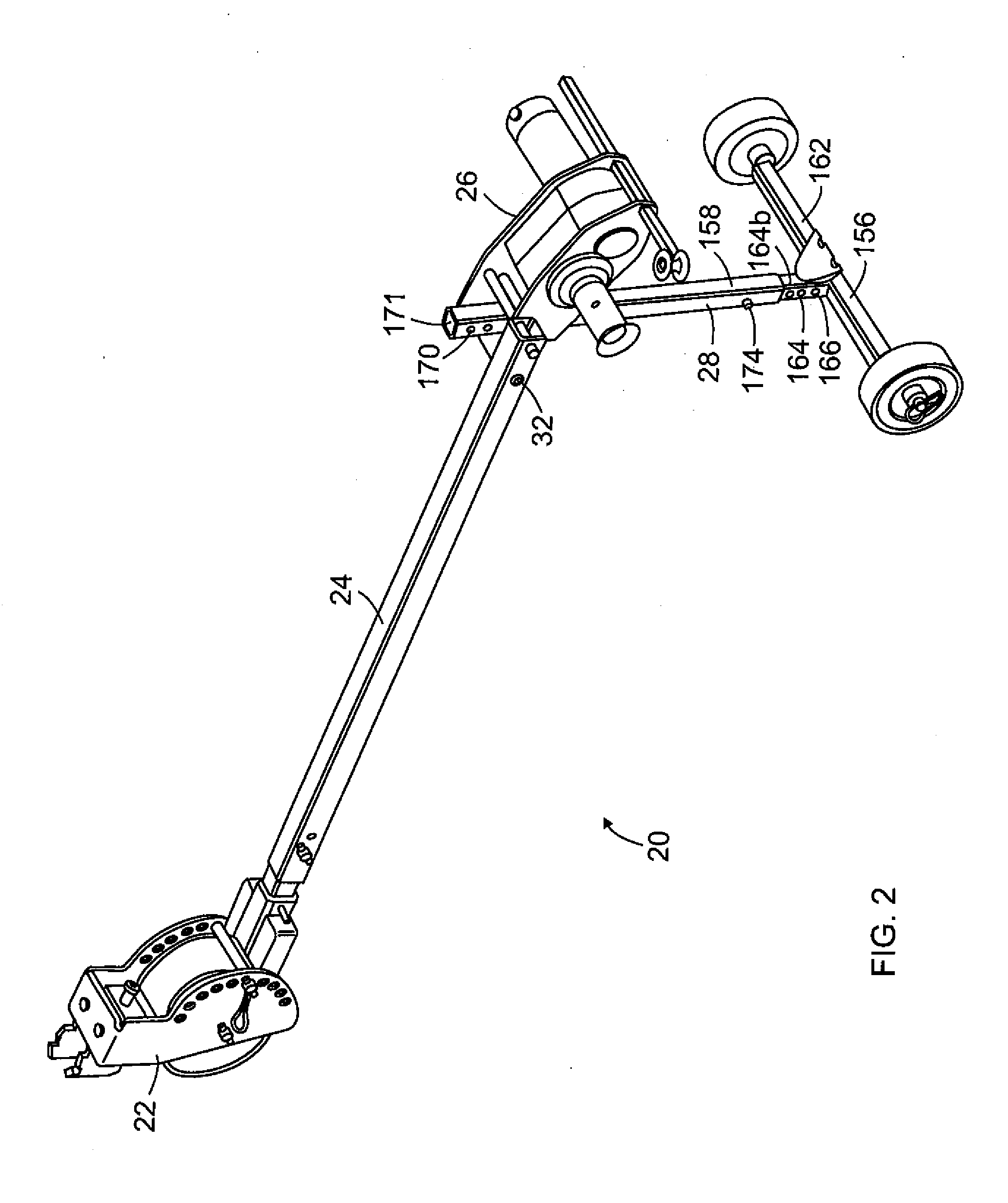
[0022]A preferred embodiment of the cable puller 20 is shown in FIGS. 1-10 and is described herein. The cable puller 20 is easily configured to pull cable up through a conduit as shown in FIGS. 1 and 9 or to pull cable down through a conduit as shown in FIGS. 2 and 10.

[0023]As best shown in FIGS. 1-2 and 9-10, the cable puller 20 includes an attachment system 22, a boom 24, a puller head 26, a base portion 28, a securing pin 30 for securing the attachment system 22 to the boom 24, and a pivot shaft 32 for pivotally attaching the boom 24, puller head 26, and base 28. In describing the cable puller 20, the...


PUM


Abstract

A puller head and cable puller including the puller head are provided for pulling cable in an upward or a downward direction. The puller head includes a frame, a capstan mounted to the frame, and first and second retaining shaft apertures. The puller head is pivotally mounted to a boom of the cable puller through a pivot shaft. The capstan of the puller head is positioned rearward of the boom. The position of an upper most surface of the capstan relative to the boom is changed by pivoting the puller head between upward and downward pulling positions. The puller head is maintained in either the upward or downward pulling position through the use of a retaining shaft.

Description

[0001]This application claims the domestic benefit of U.S. Provisional Application Ser. No. 60 / 973,796 filed on Sep. 20, 2007, which disclosure is hereby incorporated by reference.FIELD OF THE INVENTION[0002]This invention is generally directed to a cable puller which can be easily configured to pull cable upwardly or downwardly.BACKGROUND OF THE INVENTION[0003]Cable pulling is a commonly used technique whereby a pulling rope is attached to a cable or wire that is to be pulled through conduit by a cable puller. The pulling rope is wound by a user around a capstan and tails off the capstan. The capstan is powered by a motor and acts as a frictional force multiplier. The motor and capstan are usually referred to as being part of the puller head of the cable puller. Use of the cable puller to pull the cable through the conduit allows the user to exert only a small force on the rope that tails off of the capstan. This relatively small force is translated into a large force of several th...

Claims


Application Information

Patent Timeline
Patent Type & Authority Applications(United States)
IPC IPC(8): E21C29/16F16D1/00
CPCY10T403/57H02G1/08
Inventor PLUMMER, JEFFREY J.
Owner GREENLEE TEXTRON
Why Eureka
Try Eureka