Apparatus and method for generating a monocycle

a monocycle and apparatus technology, applied in the field of apparatus and methods for generating monocycles, can solve the problems of reducing the flexibility of this approach, reducing the cost of low-cost applications, and few high-speed monocycle generators, and achieving the effect of simple and cheap use and easy reproduction

a monocycle and apparatus technology, applied in the field of apparatus and methods for generating monocycles, can solve the problems of reducing the flexibility of this approach, reducing the cost of low-cost applications, and few high-speed monocycle generators, and achieving the effect of simple and cheap use and easy reproduction

US20090080493A1Inactive Publication Date: 2009-03-26AGENCY FOR SCI TECH & RES

Image

  • Apparatus and method for generating a monocycle
  • Apparatus and method for generating a monocycle
  • Apparatus and method for generating a monocycle

Examples


Embodiment Construction

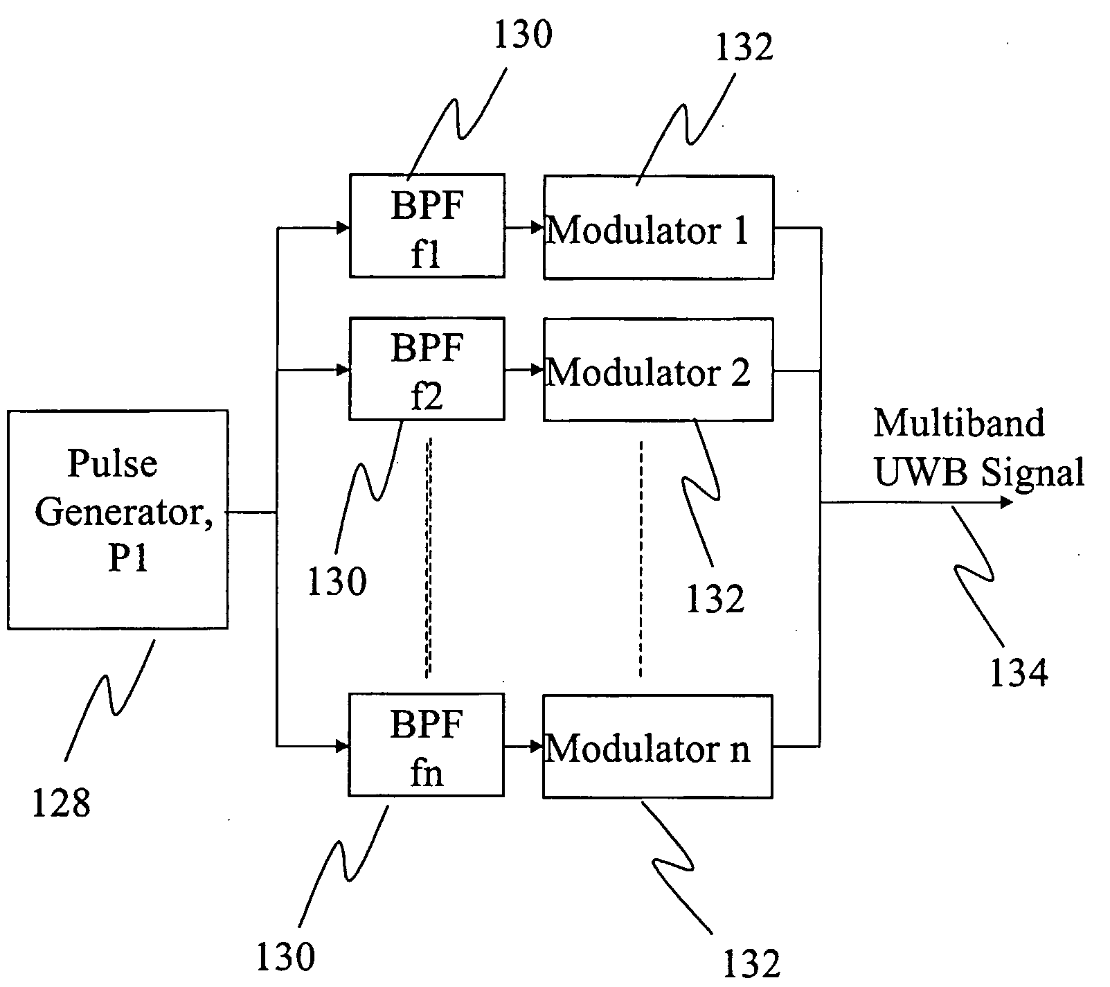
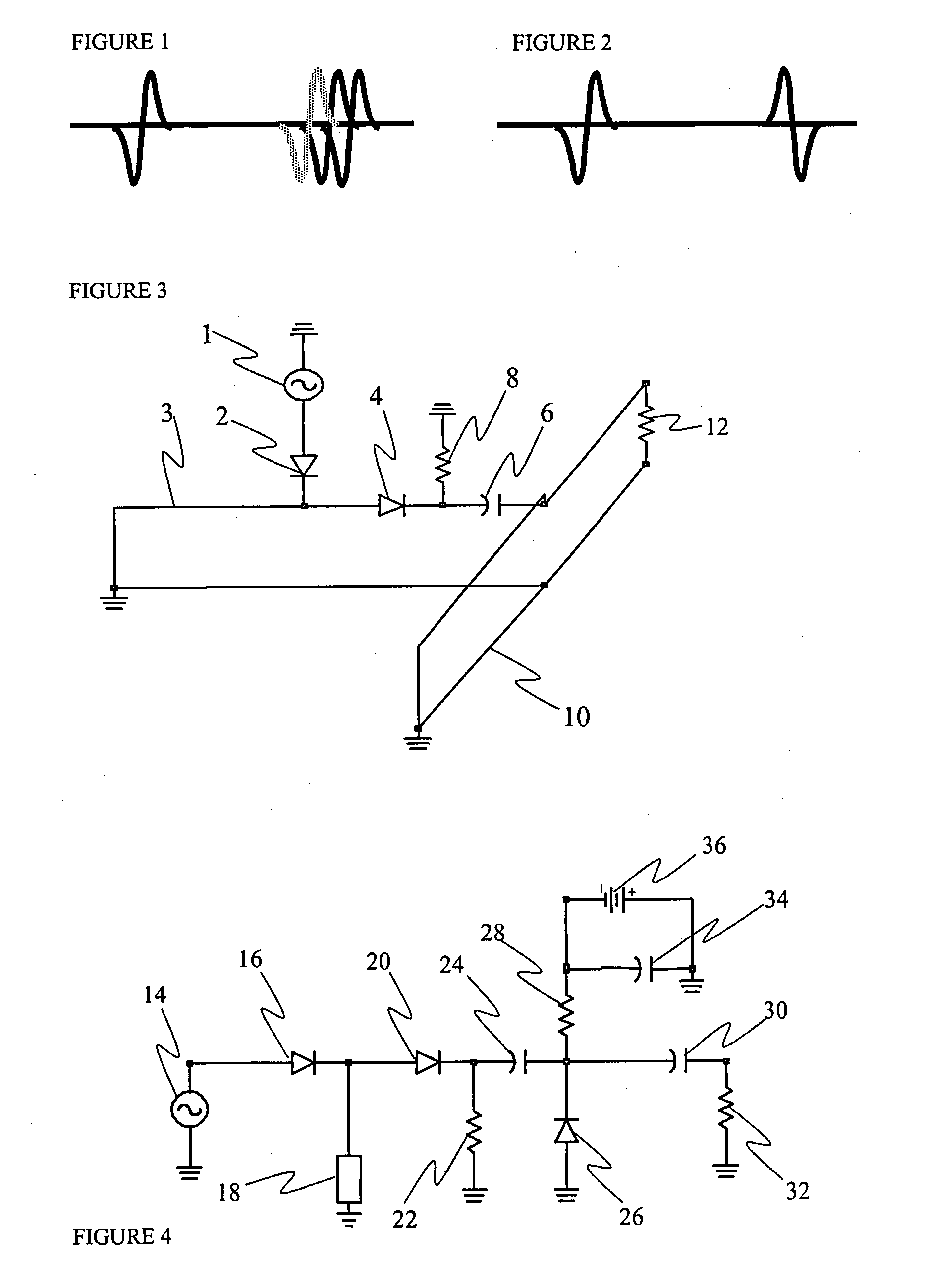
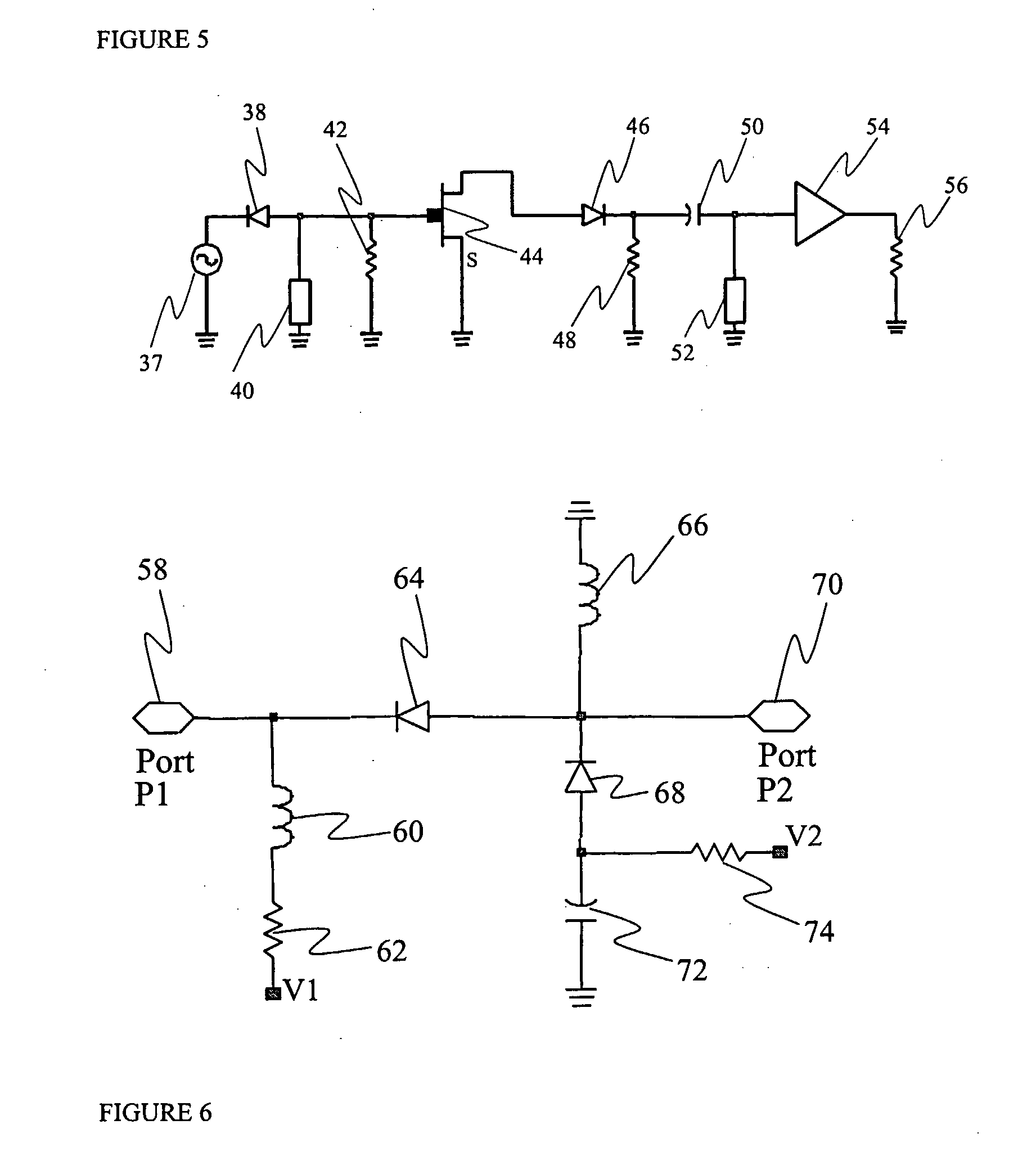
[0067]FIGS. 1 to 6 show conventional circuits for producing monocycles and / or pulses and associated waveforms. These circuits have been described above in the Background of The Invention section.

[0068]The methods and devices which illustrate preferred embodiments of the invention will be explained with reference to FIGS. 7 to 23.

[0069]Preferred embodiments of the invention relate to the generation of narrow monocycles using step recovery diodes (SRDs). These monocycles are suitable for Ultra Wideband applications. Preferably, the embodiments of the invention make use of the reverse recovery phenomenon of the SRD to generate fast transitions, and preferably use distributed microstrip elements to generate very narrow monocycle pulses from these transitions.

[0070]The SRD has the ability to store charge and to change impedance levels very rapidly. During the forward biased condition, the SRD conducts and stores the charge. When the biasing changes from the forward biased condition to th...


PUM


Abstract

An apparatus for generating a monocycle comprises an input signal source (76) for providing an input signal, and a step recovery diode (SRD) (80) for receiving the input signal and producing an impulse. A shunt inductor (102) is provided to act as a first differentiator and a capacitor (92) connected in series to the output of the step recovery diode acts as a second differentiator. The first and second differentiators are arranged to double differentiate the impulse to produce a monocycle.

Description

FIELD OF THE INVENTION[0001]The present invention relates to apparatus and methods for generating a monocycle, for use, for example, in Ultra Wideband (UWB) systems.BACKGROUND OF THE INVENTION[0002]Ultra Wideband (UWB) technology, which is useful for both communication and sensing applications, is based on very short pulses and time domain signal processing. A very commonly used pulse in UWB systems is the monocycle and as the monocycle's width determines the bandwidth, a narrow pulse width is necessary for producing an ultra wideband signal.[0003]There are several methods of generating pulses and devices used for pulse generation include, for example, tunnel diodes, avalanche transistors, and step recovery diodes (SRDs). In Ultra Wideband (UWB) applications, each pulse may represent a symbol. In a typical UWB application, the pulses are followed by a silence period (a space). The characteristics of the pulse are changed to represent the data.[0004]FIG. 1 shows conventional pulse po...

Claims


Application Information

Patent Timeline
26 Mar 2009
Publication
US20090080493A1
IPC
H03K5/01; H04B1/69
CPC
H03K4/92; H04B1/7174; H04B1/7172
Inventors
KRISHNAN, SIVANAND; VASUDEVAN PILLAI, KUMAR