Clamp

a clamping and tang technology, applied in the field of clamps, can solve the problems of affecting the use of the clamp, the clamp is awkward, and the clamp is difficult to use, and achieves the effect of preventing the tang from over-tightening

Active Publication Date: 2009-04-16
BIO PURE TECH LTD
View PDF5 Cites 13 Cited by
  • Summary
  • Abstract
  • Description
  • Claims
  • Application Information

AI Technical Summary

Benefits of technology

[0011]Advantageously, the second tang may be provided with at least one projection to mate on the first tang, to prevent over-tightening of the clamp tangs.

Problems solved by technology

However, for clamps of a larger size, I found that the hinge starts to fail on prolonged use.
While using the same screw and nut arrangement at both sides of the clamp provides a secure clamp, such a clamp is awkward, difficult to use and cannot be used one-handed.

Method used


Image

  • Clamp
  • Clamp

Examples


Embodiment Construction

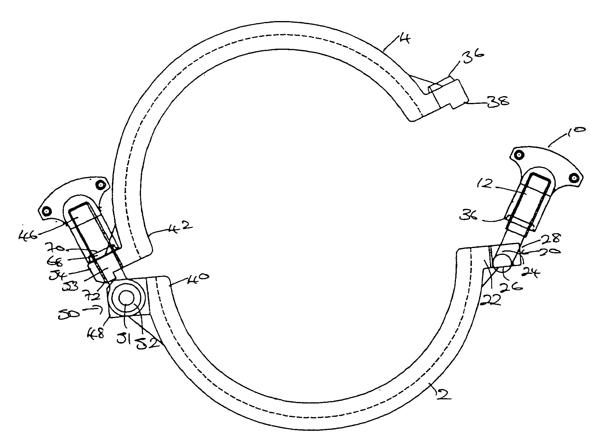
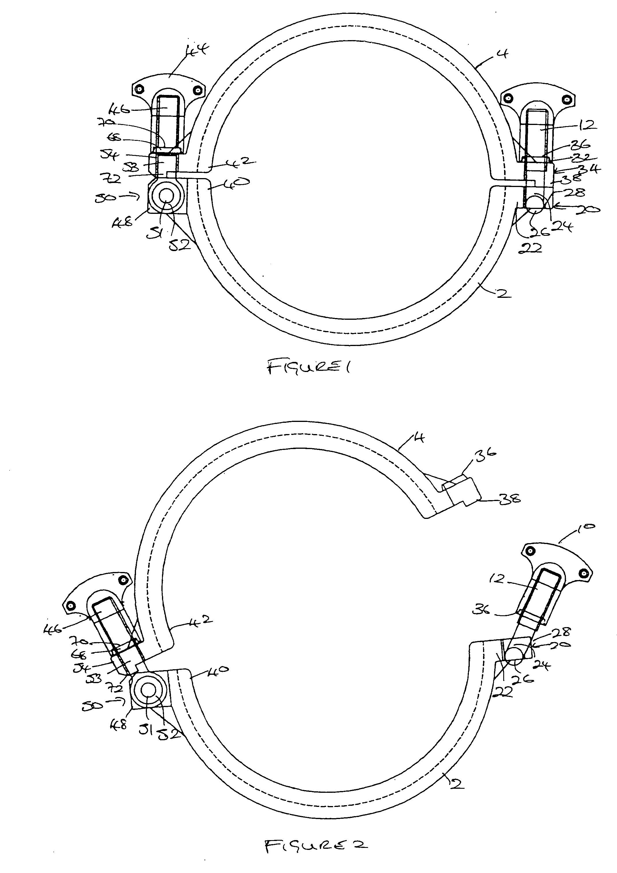
[0015]Referring to FIGS. 1 and 2, the clamp thereshown is for clamping flanged tubes, particularly for use in the pharmaceutical and food industries.

[0016]The clamp comprises a pair of substantially semi-circular tangs 2, 4. The tangs have a tapered 6 groove running around the inside of them, to engage the flanges of a pair of flanged tubes with a seal therebetween, not shown, holding the tubes in sealing relationship with each other.

[0017]At one side, the tangs 2, 4 are held together with a nut 10 and screw 12 as described in my earlier patent GB 2361753. One tang 2 has a clevis 20 defined by two lugs 22. Each had an overhung recess 24 into which the crosshead 26 of the screw 12 clips. A cross-bar 28 connects the lugs remote from their tang, whereby the screw is limited in its angular displacement about the recess. The cross-bar also stabilizes the lugs against relative displacement under load when the nut is tightened.

[0018]The other tang 4 has a part conical formation 30 on lugs ...


PUM


Abstract

A clamp for connecting flanged tubes comprising a pair of tangs having a tampered groove around their insides to engage the flanges. One of the tangs is provided with a pivotally connected screw, which passes through an aperture in one end. A nut attached to the screw holds the tangs in position. To prevent rotation of the tang about the screw, the lower shaft of the screw is provided in a non-circular shape, with the aperture in the tang being provided in mating conformity.

Description

BACKGROUND OF THE INVENTION[0001]1. Field of Invention[0002]The present invention relates to clamps, particularly though not exclusively for connecting flanged tubes for use in the pharmaceutical, food and related industries.[0003]2. Description of the Related Art[0004]In my earlier patent, GB 2361753, I describe a clamp for connecting flanged tubes. This clamp is very successful for connecting flanged tubes of up to and including approximately four inches in diameter. However, for clamps of a larger size, I found that the hinge starts to fail on prolonged use.[0005]While using the same screw and nut arrangement at both sides of the clamp provides a secure clamp, such a clamp is awkward, difficult to use and cannot be used one-handed.SUMMARY OF THE INVENTION[0006]The object of the present invention is to provide an improved joint for a clamp or the like.[0007]According to the invention there is provided a joint for a clamp or the like, having a pair of tangs, the joint including a s...

Claims


Application Information

Patent Timeline
Patent Type & Authority Applications(United States)
IPC IPC(8): F16L23/00
CPCF16L23/10
Inventor MAUNDER, ROY PETER
Owner BIO PURE TECH LTD
Why Eureka
Try Eureka