Swivel joint for lighting fixture

a technology of lighting fixtures and joints, applied in the field of swing joints for lighting fixtures, can solve the problems of the number of tools typically required to service or replace components of fixtures, the danger of maintenance workers precariously climbing, and the number of tools required to service or replace fixtures

Active Publication Date: 2009-07-30
THOMAS & BETTS INT INC
View PDF18 Cites 11 Cited by
  • Summary
  • Abstract
  • Description
  • Claims
  • Application Information

AI Technical Summary

Benefits of technology

[0014]In a preferred embodiment, the light fixture further includes a locking bolt centrally coupling the upper swivel joint member to the lower swivel joint member. The locking bolt defines a centerline of rotation between the upper and lower swivel joint members and is adapted to be selectively tightened to lock the upper swivel joint member to the lower swivel joint member, thereby preventing rotation therebetween. In this regard, each of the upper and lower swivel joint members preferably includes an internal sleeve for receiving the locking bolt. The sleeve of the upper swivel joint member makes annular contact with the sleeve of the lower swivel joint member to prevent over tightening of the locking bolt.
[0016]An index pin can also be provided to prevent rotation. Thus, each of the upper and lower swivel joint members can include at least one index pin aperture disposed adjacent a circumferential edge thereof, wherein the aperture of the upper swivel joint member aligns with the aperture of the lower swivel joint member when the swivel joint members are rotated to a desired degree. Insertion of the index pin in the aligned apertures will prevent rotation of the upper swivel joint member with respect to the lower swivel joint member.

Problems solved by technology

Obviously, a danger exists for the maintenance worker precariously climbing a ladder supported on a catwalk high above the ground.
However, one problem with the disclosed pivot joint is that its geometry causes the lighting fixture head to be pivoted laterally beyond the catwalk, thereby requiring a maintenance worker to reach outwardly over the rail of the catwalk to access the head.
Again, a danger exists for the maintenance worker, who needs to reach over the catwalk rail to access the light fixture head,
Another drawback with conventional lighting fixtures is the number of tools typically required to service or replace components of the fixture.
For example, removal of the fixture head from the mounting pole of a conventional lighting fixture may require one or more differently sized wrenches and screwdrivers to loosen and remove fixture hardware, which gives rise to another problem relating to loose hardware.
In particular, disconnecting a live plug connection of a light fixture for servicing or repair, for example, could result in an electrical arc or spark, which must be prevented in a hazardous atmosphere for safety reasons.
The drawback here is that a number of fixtures will typically be turned off at the same time during servicing of a single fixture, resulting in large areas of the facility not illuminated.
This adds to the cost of the fixture itself, as well as the cost of installation.
There also remains the possibility that the maintenance worker inadvertently fails to activate the switch before making any electrical disconnections.

Method used


Image

  • Swivel joint for lighting fixture
  • Swivel joint for lighting fixture
  • Swivel joint for lighting fixture

Examples


Embodiment Construction

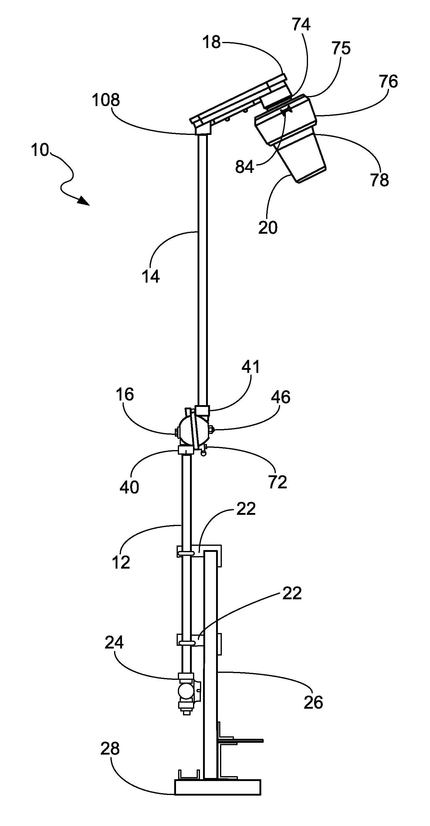
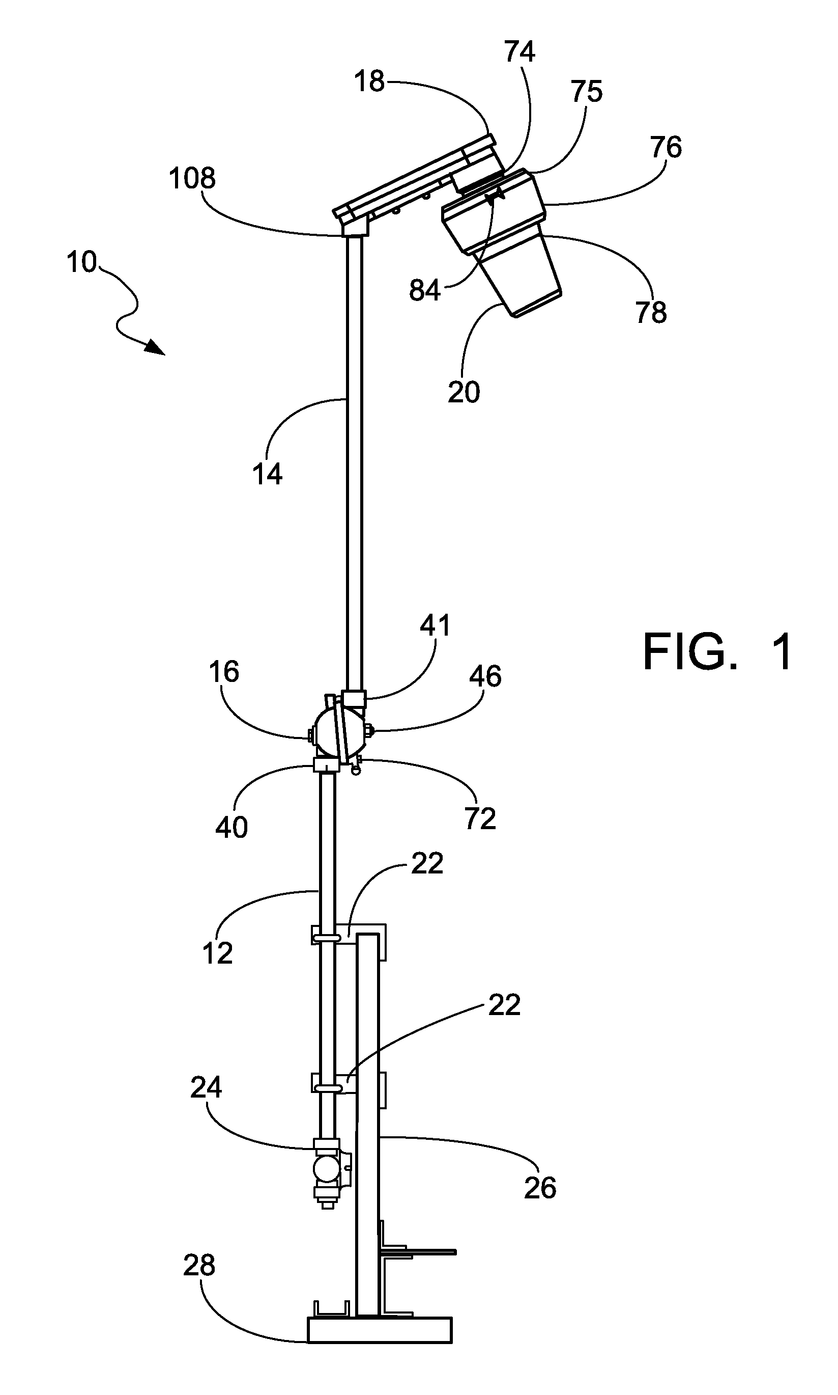
[0035]Referring first to FIG. 1, the lighting fixture 10 of the present invention generally includes a lower conduit 12, an upper conduit 14, a pivot joint 16, a stanchion arm 18, a fixture head 20, a rail mounting hardware 22 and a junction box 24. The lighting fixture 10 of the present invention is ideally adapted for mounting to a handrail 26 of a catwalk structure 28. Thus, the rail mounting hardware 22 generally includes conventional brackets, angles and bolts for securely attaching the lower conduit 12 to the rail 26. However, the invention is not limited to handrail mounting and other mounting configurations for other lighting applications are within the scope of the present invention.

[0036]The lower and upper conduits or tubes 12 and 14 are preferably tubular members made from stainless steel pipe or other durable and weather resistant material. Electrical wiring (not shown) run within the conduits 12, 14 from the junction box 24 to the fixture head 20. Additional wiring con...


PUM


Abstract

A lighting fixture swivel joint for pivoting an upper conduit having a fixture head disposed at an upper end thereof downward with respect to a lower conduit generally includes an upper swivel joint member and a lower swivel joint member rotatably coupled to the upper swivel joint member about a plane of rotation. The upper swivel joint member includes an upper conduit receptacle defined by a longitudinal axis and being adapted to receive a lower end of the upper conduit, whereby the upper conduit is coaxially aligned with the longitudinal axis. The plane of rotation is disposed at an angle of between zero degrees (0°) and thirty degrees (30°) with respect to the longitudinal axis of the upper conduit receptacle of the upper swivel joint member

Description

BACKGROUND OF THE INVENTION[0001]The present invention relates to lighting fixtures for industrial applications, and more particularly to a lighting fixture which is easily and safely accessed for servicing and repairs.[0002]In industrial applications such as mining, processing plants or refineries, there are typically long runs of piping or conveyors from one building structure to another. Often there are elevated catwalks along these long runs for maintenance purposes. Lighting fixtures are typically mounted on the catwalks to provide illumination in dark areas and at night.[0003]Typical methods for servicing or replacing components of such lighting fixtures involve use of a ladder to access the lighting fixture head, which is often supported more than eight to ten feet above the catwalk. Obviously, a danger exists for the maintenance worker precariously climbing a ladder supported on a catwalk high above the ground.[0004]One known method for providing access to the light fixture ...

Claims


Application Information

Patent Timeline
Patent Type & Authority Applications(United States)
IPC IPC(8): F21S8/02F16L27/00
CPCF21V21/26F16L27/0841
Inventor KAUFFMAN, RICK W.
Owner THOMAS & BETTS INT INC
Why Eureka
Try Eureka