

Liquid Crystal Display Device
- Summary
- Abstract
- Description
- Claims
- Application Information
AI Technical Summary
Benefits of technology
Problems solved by technology
Method used
Image

Examples
Embodiment Construction
Best Mode for Carrying Out the Invention
[0070]In the following, the best mode for carrying out the invention is described in detail in reference to the drawings.
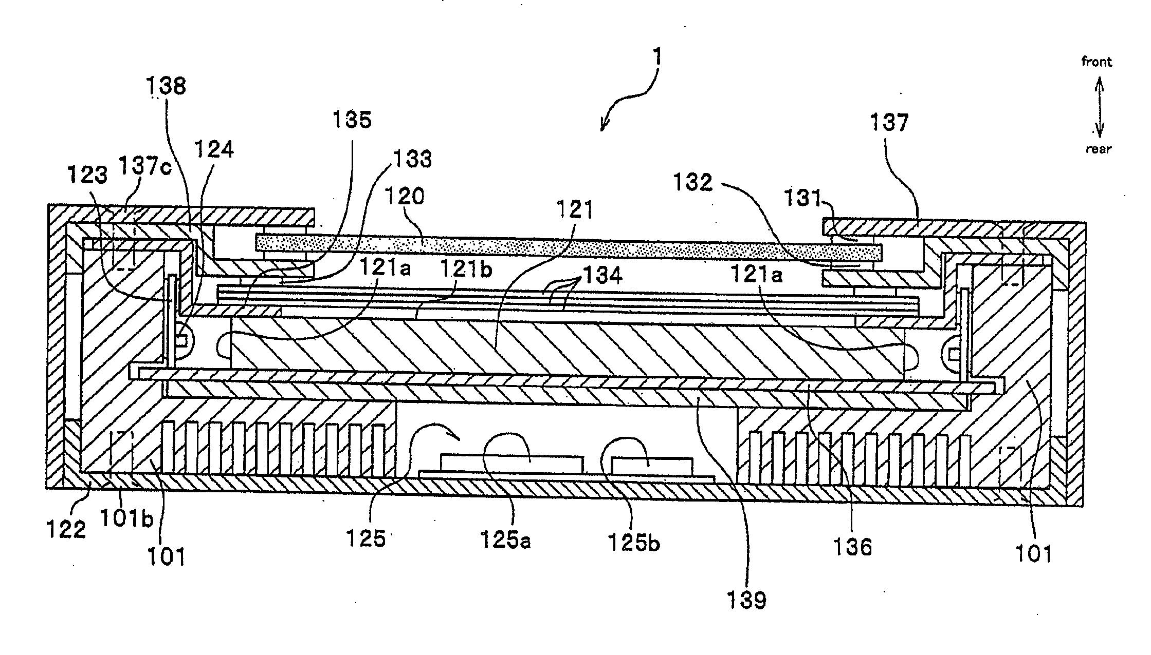
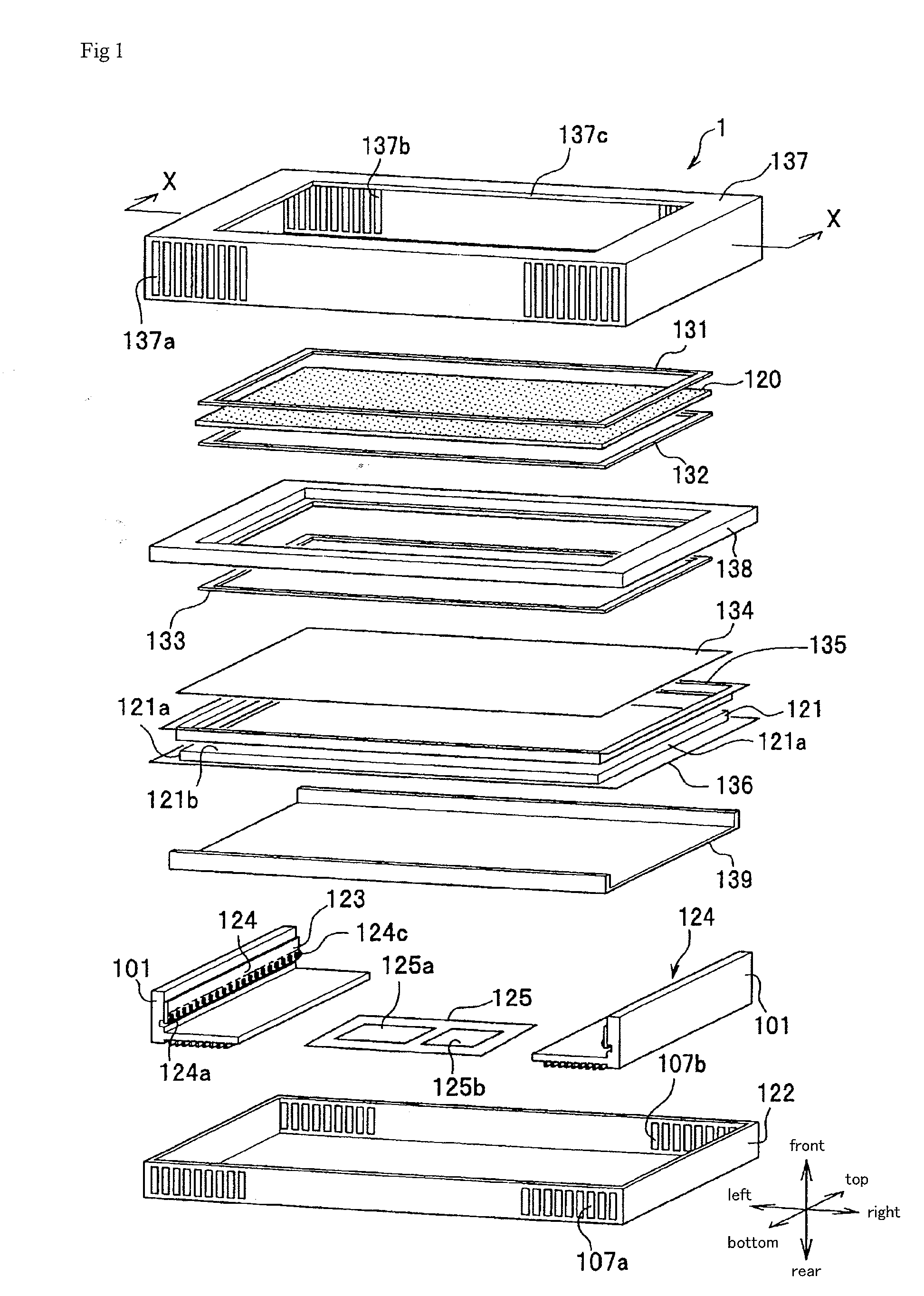
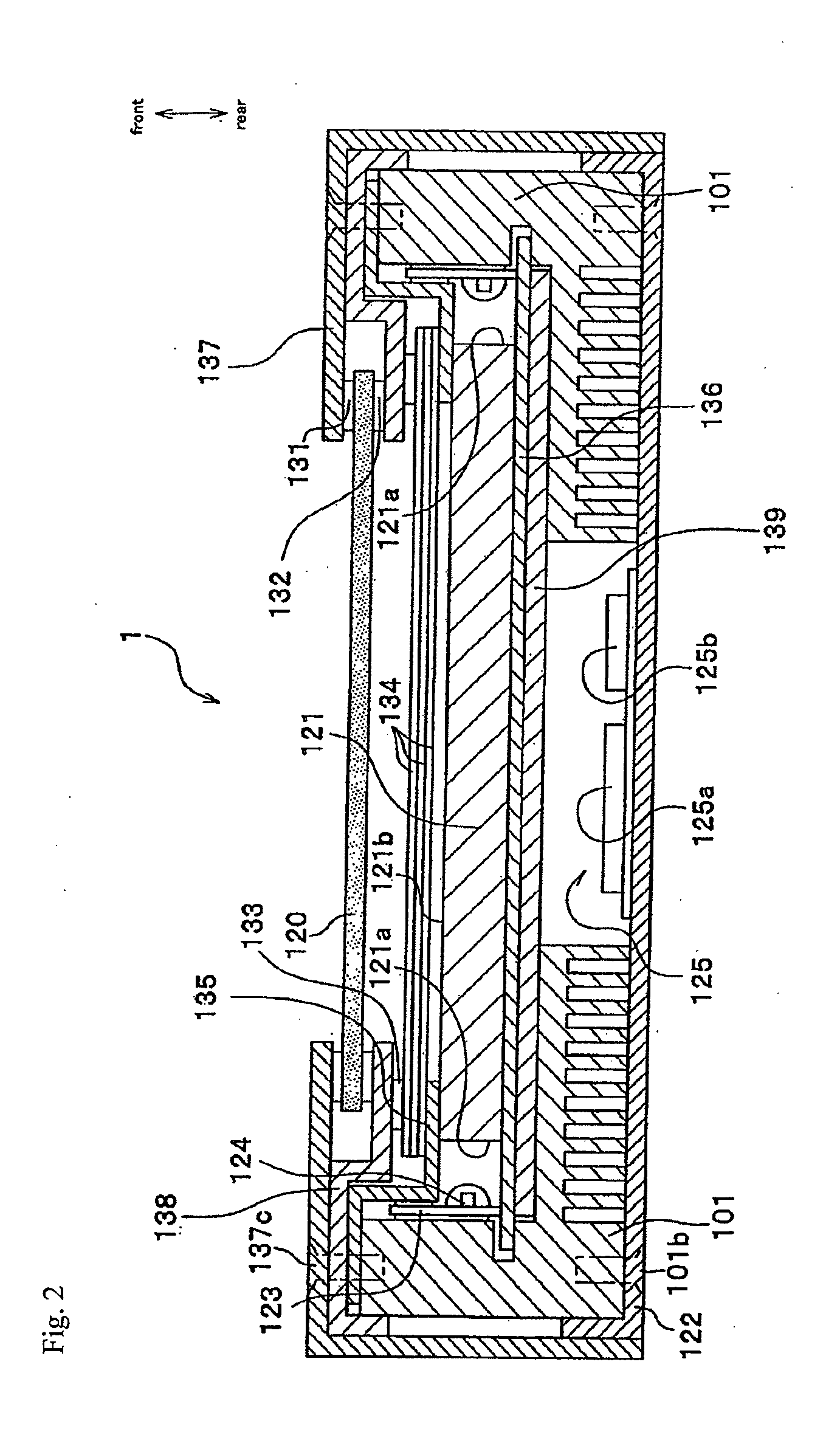
[0071]In the present embodiment, as shown in FIG. 1, the top, bottom, left, right, front and rear are defined with the display screen of a liquid crystal panel 120 as a reference.
[0072]As shown in FIG. 1, the liquid crystal display device 1 in the present embodiment is formed of a liquid crystal panel 120, a light guiding plate 121, a lower chassis 122, which is a support member, light source modules 124, lenses 124c which cover the light source of the light source modules 124, substrates 123 for mounting a light source, and a heat sink 101, which is a heat releasing member. Furthermore, the liquid crystal display device 1 is provided with a first frame 137, a first rubber cushion 131, a second rubber cushion 132, a second frame 138, an optical sheet 134, a first reflective sheet 135, a second reflective sheet 136 and an upp...
PUM
 Abstract
Description
Claims
Application Information