Structure of a single-pull reel

Inactive Publication Date: 2009-04-23
ACROX TECH
View PDF4 Cites 17 Cited by
  • Summary
  • Abstract
  • Description
  • Claims
  • Application Information

AI Technical Summary

Benefits of technology

[0015]6. The installation of the apparatus of the present inventio

Problems solved by technology

The designing of the track for the steel bead is difficult with respect to precision and the producing of a mold is laborious.
Thus, the yield of the assembly will not be improved, and the cost of production will be increased.
Another drawback is that the friction of the track 31 or the gap formed is to

Method used


Image

  • Structure of a single-pull reel
  • Structure of a single-pull reel
  • Structure of a single-pull reel

Examples


Example

[0026]The following descriptions are of exemplary embodiments only, and are not intended to limit the scope, applicability or configuration of the invention in any way. Rather, the following description provides a convenient illustration for implementing exemplary embodiments of the invention. Various changes to the described embodiments may be made in the function and arrangement of the elements described without departing from the scope of the invention as set forth in the appended claims.

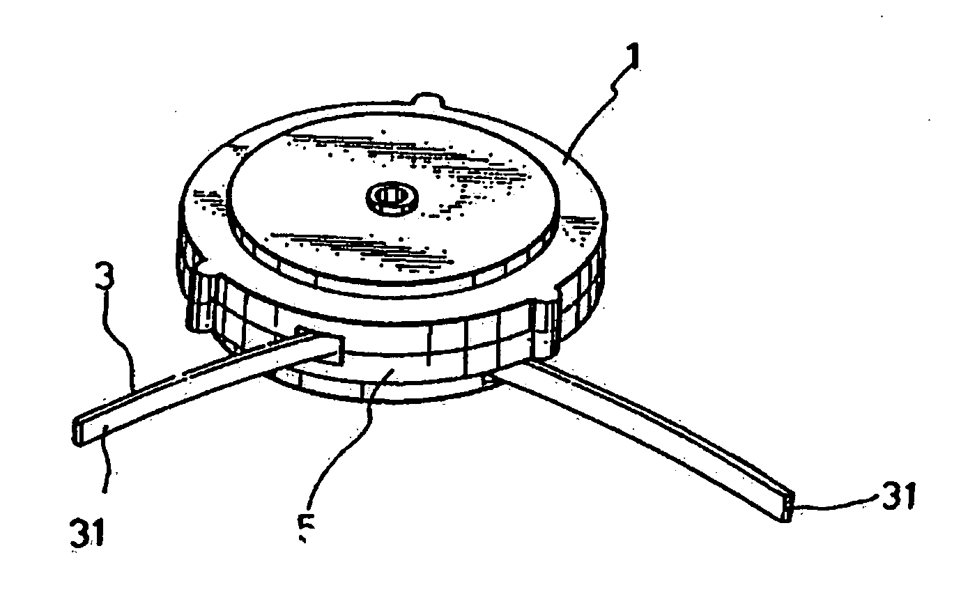
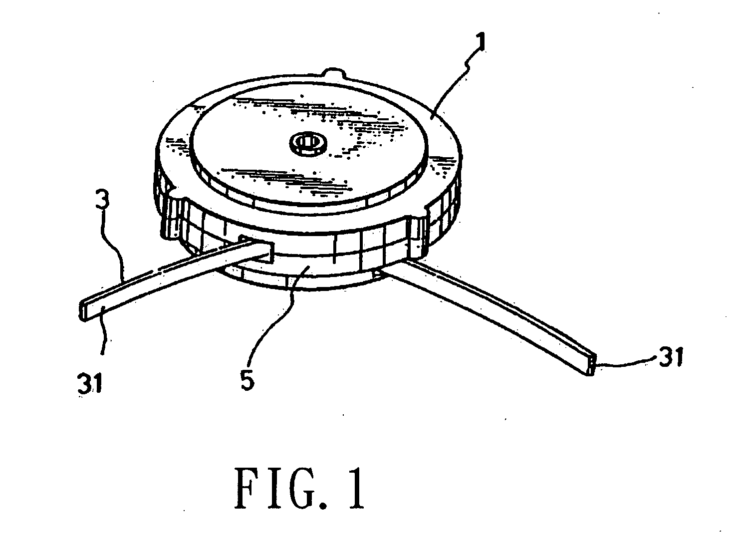
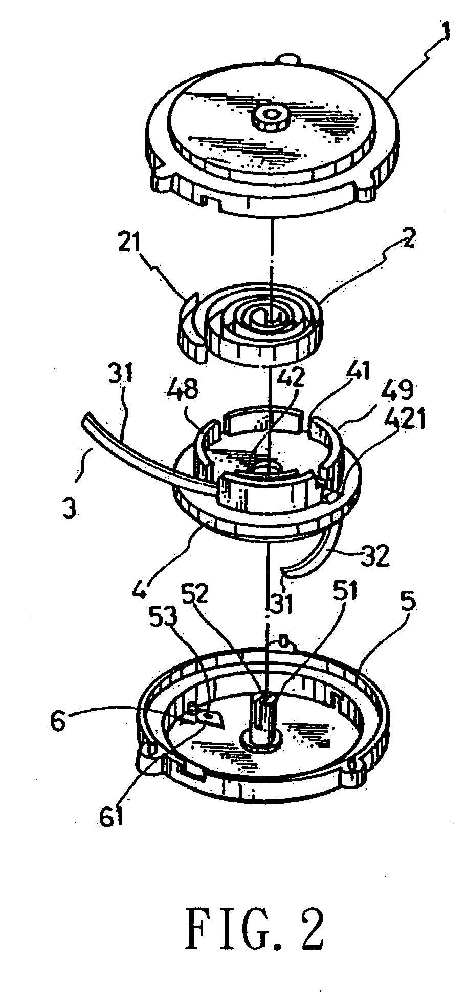
[0027]Referring to FIGS. 1, 2 and 3, the single-pull reel according to the present invention generally comprises a top cover 1, a spiral spring 2, a cord 3, a cord-rotating disc 4, a bottom cover 5 and a peg positioning structure 6. The bottom cover 5 is provided at the center with an axle 51 which has a notch 52 at the top end. The top cover 1 is configured to engage with the bottom cover 5. The inner end of the spiral spring 2 is in engagement with the engaging slot 52 of the axle 51 within the...


PUM


Abstract

A single-pull reel which includes a bottom cover having a center axle, a top cover engageable with the bottom cover; a cord-rotating disc having a top portion provided with a circular flange which is divided into a plurality of sections by a plurality of slots, a clamping member being provided behind one of the sections to form a passage therebetween and having a plurality of serrated teeth at an inner side against the one of the sections, the bottom portion being provided with a multi-operation urging track, a spiral spring having an inner end engaged with a notch of the axle and an outer end bent into a hook to engage with one of the sections of the cord-rotating disc, a cord, and a peg positioning structure comprising a peg and a pulling spring.

Description

CROSS-REFERENCE[0001]This is a continuation-in-part of the pending patent application Ser. No. 11 / 843,653.BACKGROUND OF THE INVENTION[0002](a) Technical Field of the Invention[0003]The present invention is related to an improvement in the structure of a single-pull reel.[0004](b) Description of the Prior Art[0005]FIGS. 12 and 13 show a conventional reel A10 employing a steel bead as the positioning structure. The reel A10 comprises a front cover A1, a spiral spring A2, a sliding seat A3, a transmission line A4, a steel bead A5 and a rear cover A6. In this conventional reel, the spring A2 is used to restore the transmission line A4 and a steel bead positioning structure is used. A multiple steel bead track A31 is provided at the bottom section of the sliding seat A3 to allow the steel bead A5 to roll along the track A31 and to engage. The designing of the track for the steel bead is difficult with respect to precision and the producing of a mold is laborious. Thus, the yield of the a...

Claims


Application Information

Patent Timeline
IPC IPC(8): H02G11/02B65H75/44
CPCB65H75/28B65H75/4434H02G11/02F02N3/02B65H2701/34
Inventor CHANG, WEN-HAN
Owner ACROX TECH
Why Eureka
Try Eureka