

Optical Power Monitor and its Manufacturing Method
- Summary
- Abstract
- Description
- Claims
- Application Information
AI Technical Summary
Benefits of technology
Problems solved by technology
Method used
Image

Examples
example 1
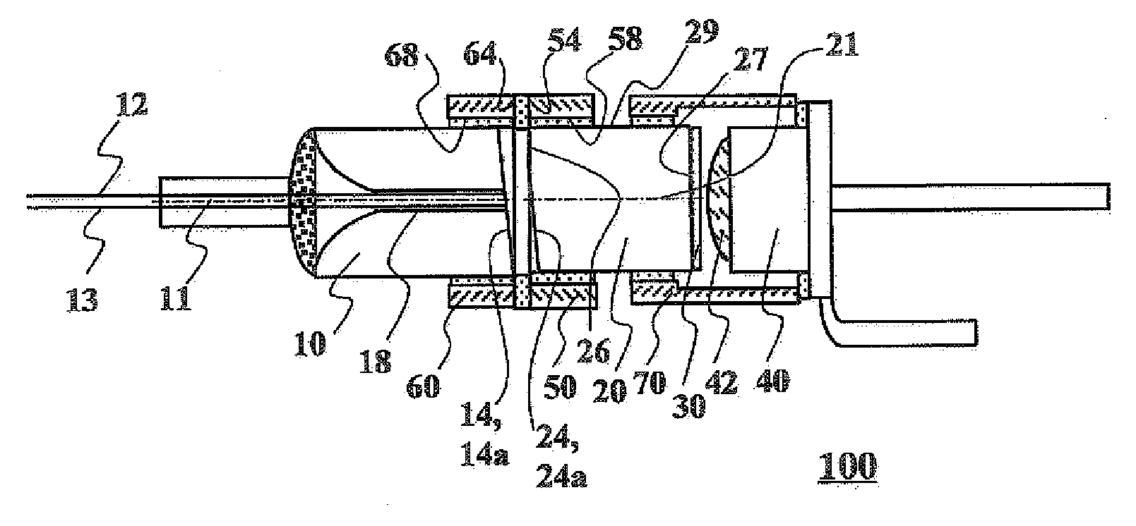
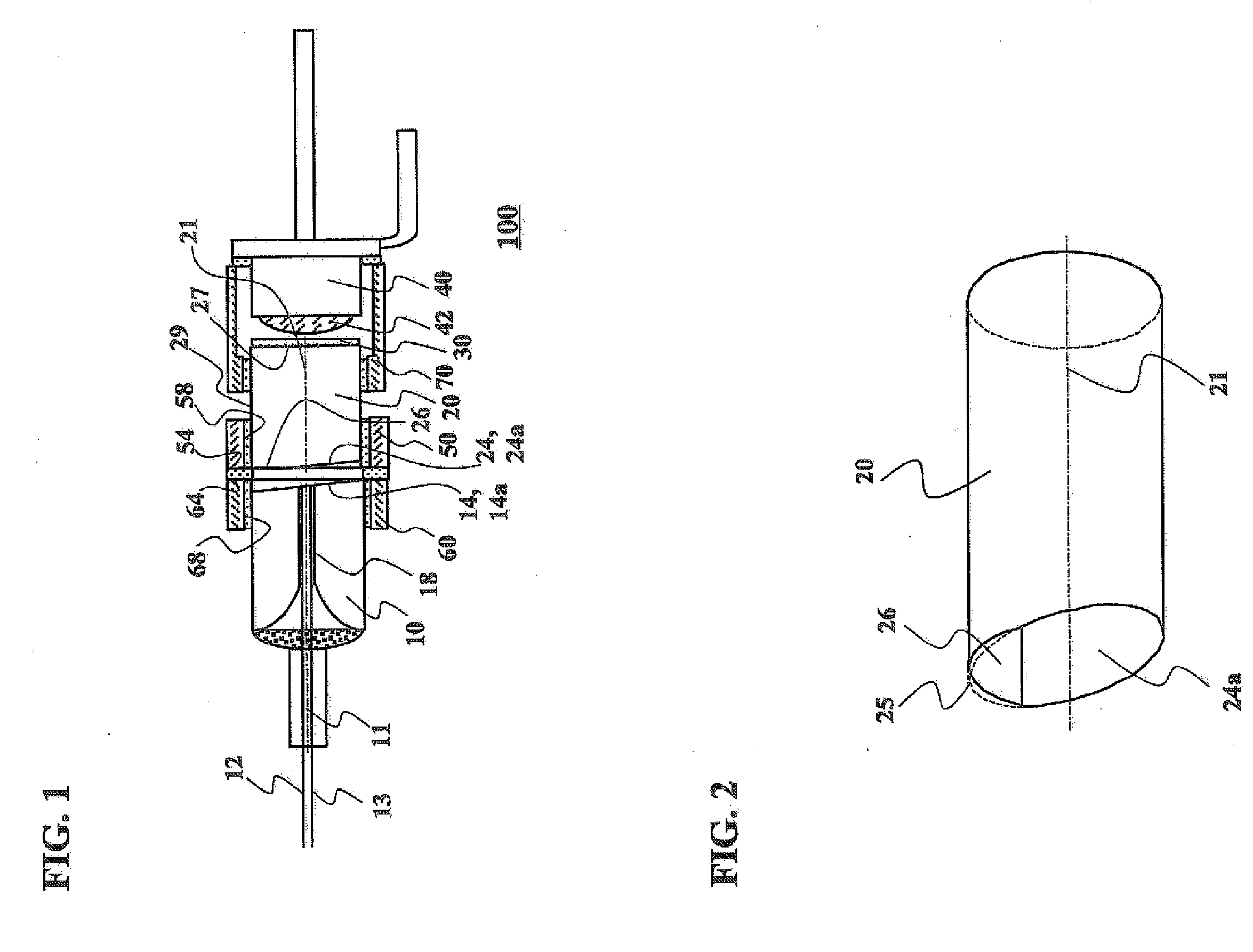
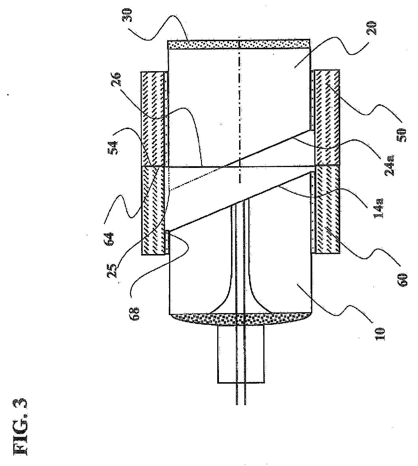
[0054] Referring to FIGS. 1 through 3, an optical power monitor 100 of EXAMPLE 1 according to the present invention includes a pig-tail fiber 10 having two optical fibers 12, 13 aligned along an axis 11 parallel to and at a small distance from each other, and a columnar GRIN lens 20 having two opposite end faces 24 and 27, wherein one end face 24 of them faces a rear end face 14 of the pig-tail fiber at a predetermined spacing from the rear end face 14 of the pig-tail fiber, and the other end face 27 has a tap film 30 formed thereon, and a photo-diode 40 provided to be opposed to the tap film 30 of the columnar GRIN lens 20. The pig-tail fiber 10 is formed of a columnar glass into which the two optical fibers are inserted and fixed, and may be called “two-core capillary with optical fibers” or “two-core capillary glass ferrule with optical fibers”. When one optical fiber 12 of the optical fibers 12 and 13 included in the pig-tail fiber 10 is an input optical fiber, the other optical...
example 2
[0067]FIG. 6 is a cross-sectional view showing a main portion (fiber lens unit) of an optical power monitor 200 of EXAMPLE 2. The optical power monitor 200 has the same structure and dimensions as the optical power monitor 100 of EXAMPLE 1. However, the optical power monitor 200 has an arc-segmental end face 16′ in an axial direction of a pig-tail fiber 10′ on a tip of an angled face 14a′ of the pig-tail fiber 10′, though the optical power monitor 100 has the arc-segmental end face 26 on the tip 25 of the angled face of the GRIN lens 20. The arc-segmental end face 16′ of the pig-tail fiber 10′ is positioned in the same plane as the end face 64 of the second sleeve 60 bonded to the pig-tail fiber 10′, and the axis 11′ of the pig-tail fiber 10′ is perpendicular to the end face 64 of the second sleeve 60. A tip 25′ of the angled face 24a′ of the GRIN lens 20′ is in a position set back from the end face 54 of the first sleeve 50. It will be understood that the optical power monitor 200 ...
example 3
[0068]FIG. 7 is a cross-sectional view showing a main portion (fiber lens unit) of an optical power monitor 300 of EXAMPLE 3. In the optical power monitor 300, the pig-tail fiber 10′ and the GRIN lens 20 both have the arc-segmental end faces 16′, 26 on the tips of their angled faces 14a′, 24a, respectively. Here, the arc-segmental end face 26 of the GRIN lens 20 is positioned in the same plane as the end face 54 of the first sleeve 50, and the axis 21 of the GRIN lens 20 is perpendicular to the end face 54 of the first sleeve 50. In the optical power monitor 300 of EXAMPLE 3, the arc-segmental end face 16′ of the pig-tail fiber 10′, instead of the GRIN lens 20, may be positioned in the same plane as the end face 64 of the second sleeve 60. It will be understood that the optical power monitor 300 has the same advantages as the optical power monitor 100 of EXAMPLE 1.
PUM
 Abstract
Description
Claims
Application Information