Conveying apparatus, liquid applying apparatus, and image forming apparatus

a technology of liquid application and conveying apparatus, which is applied in the direction of typewriters, thin material processing, printing, etc., can solve the problems of increasing the moisture difference between the front side and the back side of the recording medium, requiring a certain amount of time for waiting for the recording, and causing curling of the recording medium

Active Publication Date: 2009-04-23
RICOH KK
View PDF11 Cites 56 Cited by
  • Summary
  • Abstract
  • Description
  • Claims
  • Application Information

AI Technical Summary

Benefits of technology

[0018]It is a general object of the present invention to provide a conveying apparatus, a liquid applying apparatus, and an image forming apparatus that substantially obviate one or more of the problems caused by the limitations and disadvantages of the related art.

Problems solved by technology

For example, in using an image forming apparatus that forms an image by applying a recording liquid onto a recording medium, the image forming apparatus requires some amount of time for waiting for the recording liquid to dry.
Nevertheless, the pigment type ink has a tendency of causing curling of the recording medium.
However, since time is required for the ink to sink (soak) into the recording medium, the moisture difference between the front side and the back side of the recording medium increases.
This moisture difference leads to curling of the recording medium.
Therefore, conveying the recording medium in the curled state may cause jamming and adversely affect sheet-discharging steadiness.
This results in a poorly printed recording medium.
Furthermore, although a pigment type ink has a high quick-drying property, smudging due to insufficient drying of ink may occur depending on the formula of ink or the type of paper used.
Furthermore, the problem of drying which the pigment type ink faces is more serious in a case of using the dye type ink.
Thus, in a case where an insufficiently dried paper is conveyed, ink stains may adhere to a conveying part of an image forming apparatus.
This may cause ink stains of the conveying part to re-adhere to a conveyed paper and cause the stains on the paper to adhere to other paper.
Compared to a case of stacking the paper in a manner where the recorded side is facing upward, it is difficult to stack the paper on a discharged paper stacking part of the image forming apparatus.
However, at the same time of resolving such problems, there is also a need to prevent productivity from decreasing due to decrease of throughput caused by correcting the curling or waiting for the drying of paper.

Method used


Image

  • Conveying apparatus, liquid applying apparatus, and image forming apparatus
  • Conveying apparatus, liquid applying apparatus, and image forming apparatus
  • Conveying apparatus, liquid applying apparatus, and image forming apparatus

Examples


first embodiment

[0049]First, an image forming apparatus (which is also a liquid applying apparatus) 1000 having a conveying apparatus 7 according to the present invention is described with reference to FIGS. 1-4.

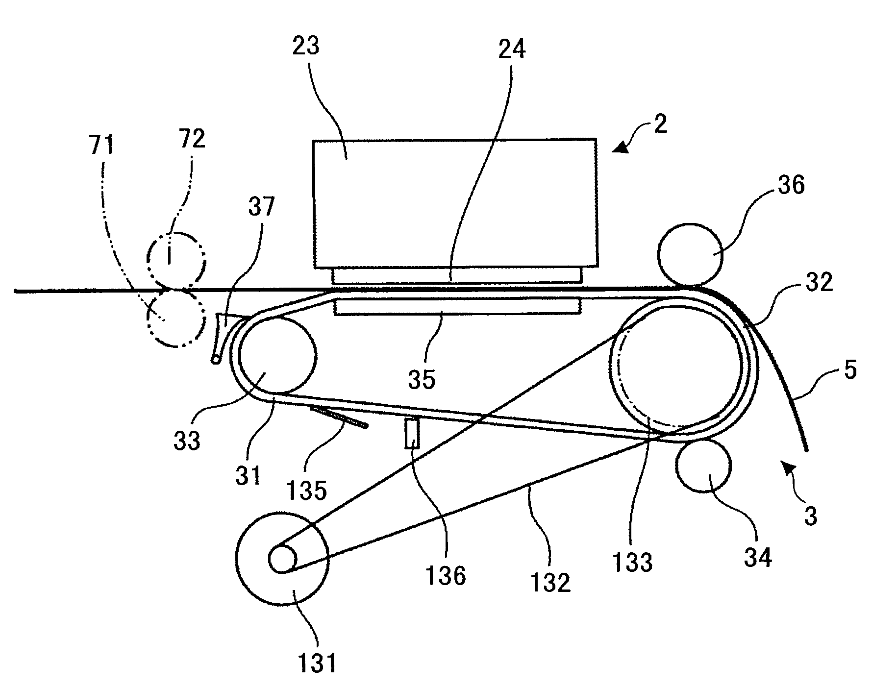
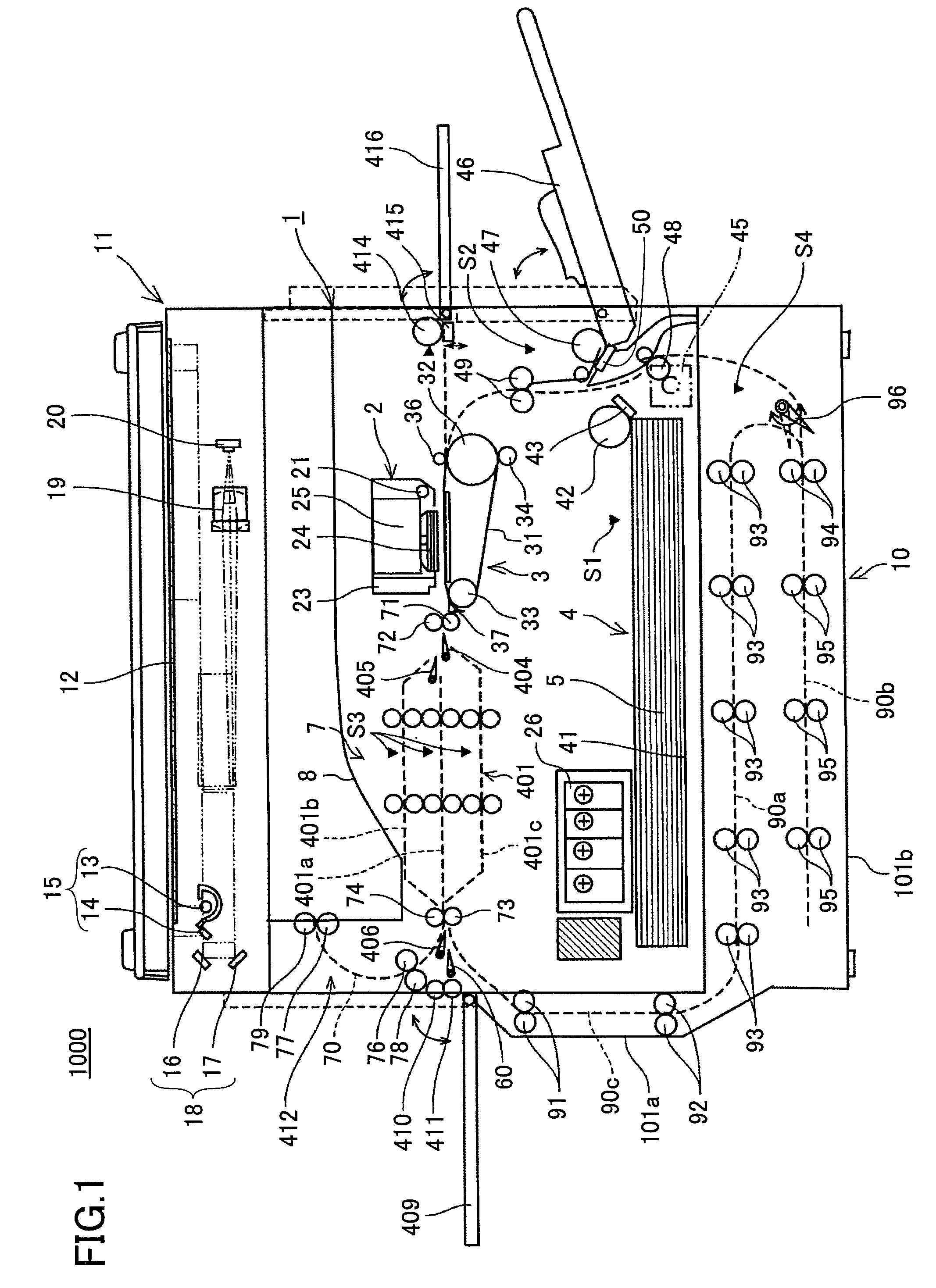
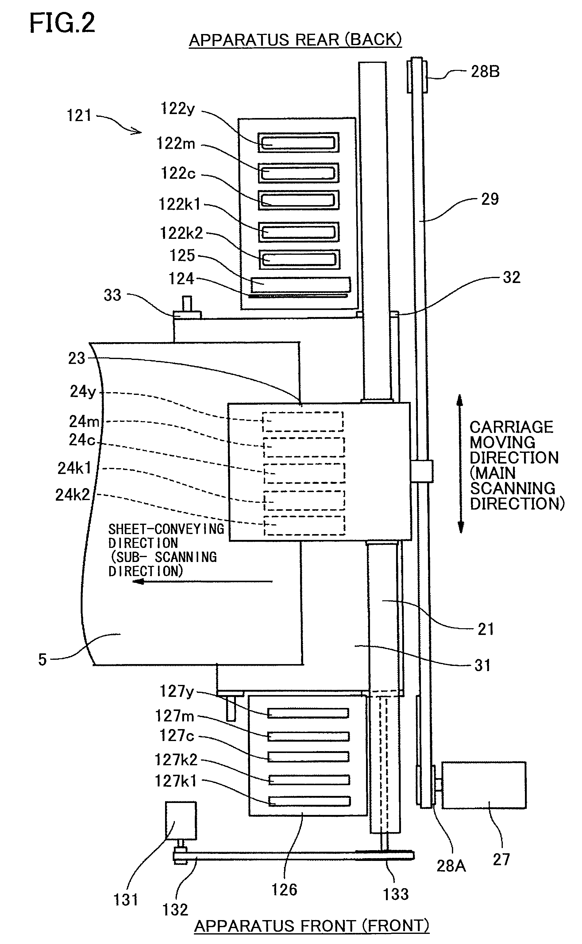
[0050]FIG. 1 is a schematic diagram showing an exemplary overall configuration of the image forming apparatus 1000. FIG. 2 is a plan view of an image forming part 2 and a sub-scan conveying part 3 of the image forming apparatus 1000. FIG. 3 is a side view of the image forming part 2 and the sub-scan conveying part 3 of the image forming apparatus 1000. FIG. 4 is a schematic view showing a portion of a conveying part (conveying apparatus) 7.

[0051]The image forming apparatus 1000 has a main body 1. The main body 1 of the image forming apparatus 1000 has installed, for example, the image forming part 2 for forming images and the sub-scan conveying part 3. In the image forming apparatus 1000, paper (conveyance object) 5 is fed sheet by sheet from a sheet feed part 4 provided at a bottom portion...

second embodiment

[0143]Among the first-third conveyance paths 401a-401c included in the conveyance path 401, the first conveyance path (straight conveyance path) 401a is provided as the uppermost conveyance path according to the present invention. This facilitates the fixing of jamming in the first conveyance path (most frequently used conveyance path among the conveyance paths) 401a.

[0144]Furthermore, the sheet-discharge part 412 according to the second embodiment of the present invention has a sheet-discharge conveyance path 70 including a first sheet-discharge conveyance path 70a, a second sheet-discharge conveyance path 70b, and a third sheet-discharge conveyance path 70c.

[0145]The sheet discharge part 412 according to the second embodiment of the present invention includes: a pair of conveying rollers 73 and 74; a first branching plate 406; a second branching plate 60; a third branching plate 407; a fourth branching plate 408; plural sheet-discharge conveying rollers 78, 82, and 86; plural sp...

fourth embodiment

[0153]Alternatively, the length of the first and second conveyance paths 70f, 70g allows two sheets of paper 5 to be placed on a single conveyance path. In other words, a total of four sheets of paper 5 can be put in a standby state on the first and second conveyance paths 70f, 70g (L2≧L1×2). In a case of distributing (conveying) four sheets of paper 5 (fed in an order from paper 5A to paper 5D), the first and second papers 5A and 5B are conveyed to the first conveyance path 70f and put in a standby state on the first conveyance path 70f. Then, the third and fourth papers 5C and 5D may be conveyed to the second conveyance path 70g and put in a standby state on the second conveyance path 70g. Alternatively, the third and fourth paper 5C and 5D may be alternately conveyed to the first and second conveyance paths 70f and 7g, and put in a standby state on the first and second conveyance paths 70f and 70g, respectively. It is, however, to be noted that the method for conveying and puttin...


PUM

PropertyMeasurementUnit
viscosityaaaaaaaaaa
angleaaaaaaaaaa
distanceaaaaaaaaaa

Abstract

A disclosed conveying apparatus includes plural conveyance paths arranged in parallel and configured to receive plural conveyance objects fed from an upstream side of the plural conveyance paths and convey the received plural conveyance objects to a conveyance destination situated at a downstream side of the plural conveyance paths. The plural conveyance paths are configured to convey the plural conveyance objects in the order in which the plural conveyance objects are received.

Description

TECHNICAL FIELD[0001]The present invention relates to a conveying apparatus, a liquid applying apparatus, and an image forming apparatus.BACKGROUND ART[0002]Image forming apparatuses such as printers, facsimiles, copiers, and multi-function machines having the functions of a printer, a facsimile, and a copier, form images by conveying a medium (hereinafter also referred to as “paper”) and applying a liquid (hereinafter also referred to as “recording liquid” or “ink”) onto the medium. In forming the images, the image forming apparatus uses, for example, a liquid applying apparatus (e.g., liquid jet apparatus) including a recording head having a liquid jet head for jetting droplets of liquid (recording liquid). It is to be noted that image forming may also be referred to as recording, printing, image printing, or character printing. It is also to be noted that the material of the medium is not limited to a particular material. Thus, the medium may be also be referred to as a sheet of ...

Claims


Application Information

Patent Timeline
Patent Type & Authority Applications(United States)
IPC IPC(8): B41J2/01
CPCB41J3/44B41J3/60B65H2801/06B65H2513/54B65H2513/50B65H2511/25B65H2407/311B41J11/0015B41J11/002B41J11/0025B41J11/007B41J11/0085B41J11/0095B41J13/0018B41J13/0036B41J13/0045B41J13/0054B41J13/103B41J13/106B65H29/60B65H2301/4454B65H2301/4455B65H2301/517B65H2220/02B65H2220/01B65H2701/176B41J11/0021B41J11/0022B41J11/0024B65H2407/30B65H2513/52
Inventor IMOTO, SHINJI
Owner RICOH KK
Why Eureka
Try Eureka