
Electrowetting Display Devices

Inactive Publication Date: 2009-04-23
IND TECH RES INST
View PDF7 Cites 48 Cited by
  • Summary
  • Abstract
  • Description
  • Claims
  • Application Information

AI Technical Summary

Problems solved by technology

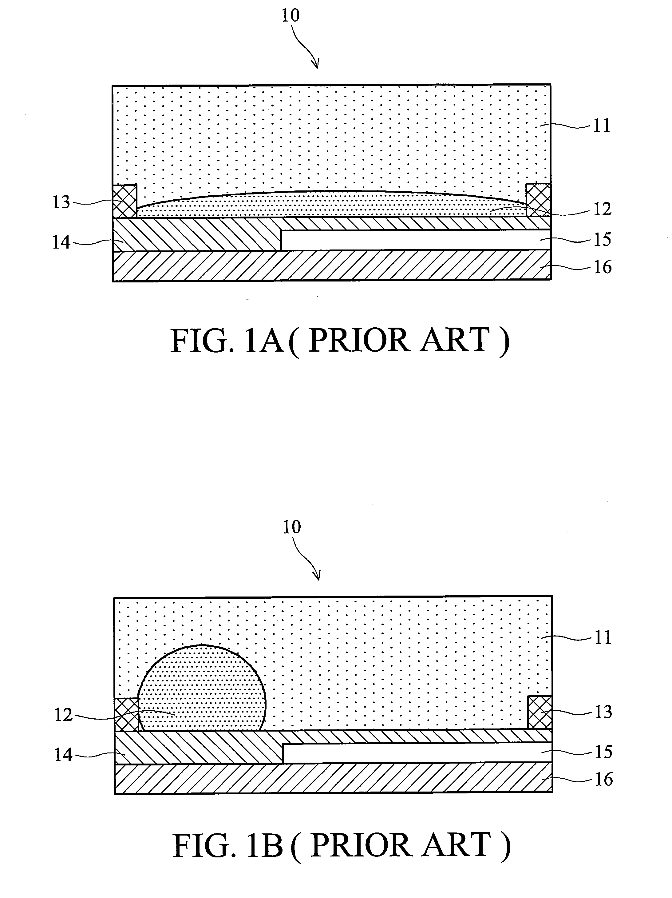
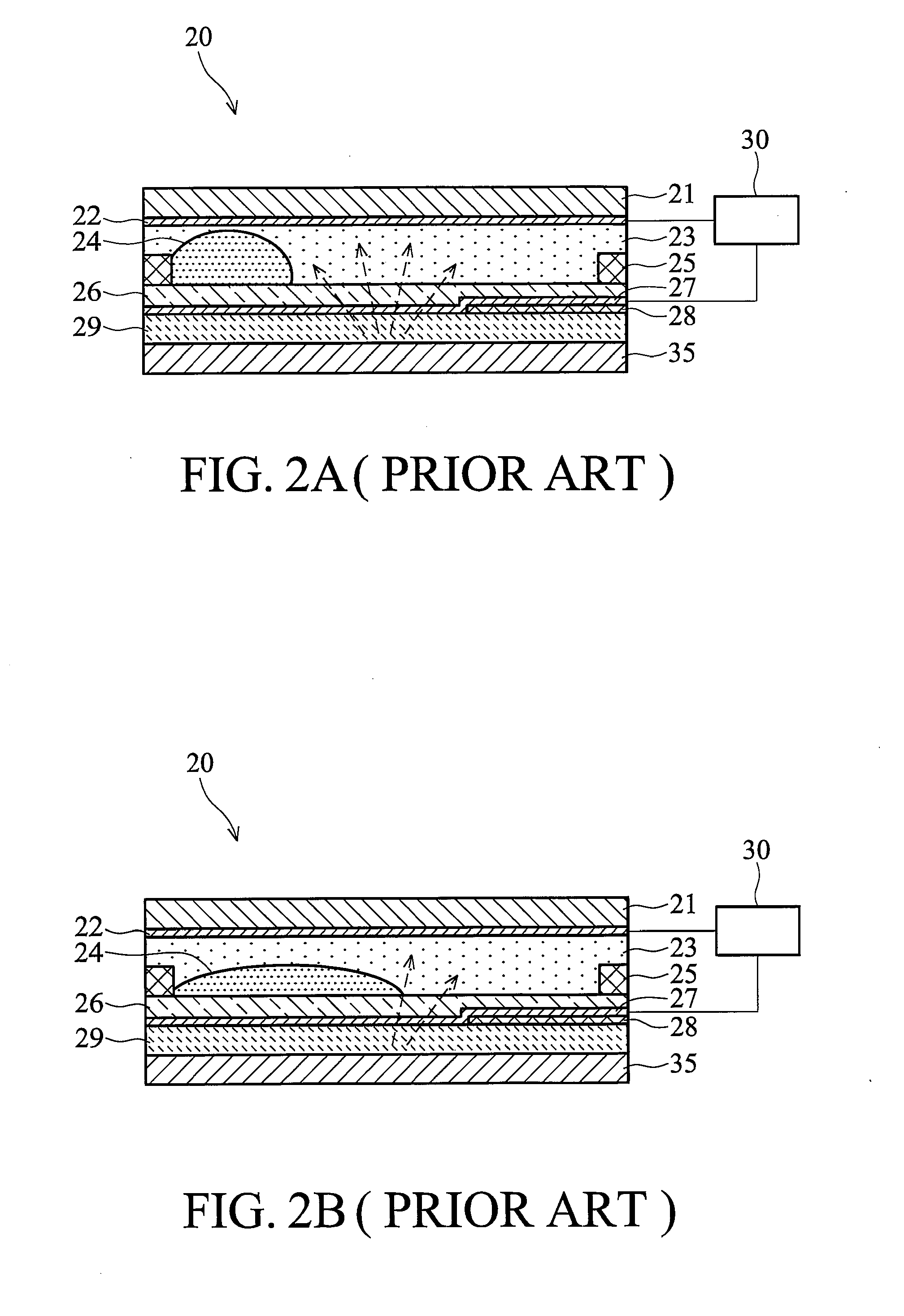
The reflective regions and transmission regions of the conventional transflective color electrowetting display, however, are improperly arranged such that gray scale of the electrowetting display becomes difficult to control.
Therefore, the stability and quality of electrowetting displays are affected by gray scale variations.
As the applied voltage increases, pixels of the conventional transflective electrowetting display exposes the reflective region prior to the transmission region, resulting in gray scale variations and gray scale control difficulties under outdoor and indoor ambient environments.
Furthermore, the stability and quality of the electrowetting display are affected by gray scale variations.

Method used


Image

  • Electrowetting Display Devices
  • Electrowetting Display Devices
  • Electrowetting Display Devices

Examples


Embodiment Construction

[0029]It is to be understood that the following disclosure provides many different embodiments, or examples, for implementing different features of various embodiments. Specific examples of components and arrangements are described below to simplify the present disclosure. These are merely examples and are not intended to be limiting. In addition, the present disclosure may repeat reference numerals and / or letters in the various examples. This repetition is for the purpose of simplicity and clarity and does not in itself indicate a relationship between the various embodiments and / or configurations discussed. Moreover, the formation of a first feature over or on a second feature in the description that follows may include embodiments in which the first and second features are formed in direct contact or not in direct contact.

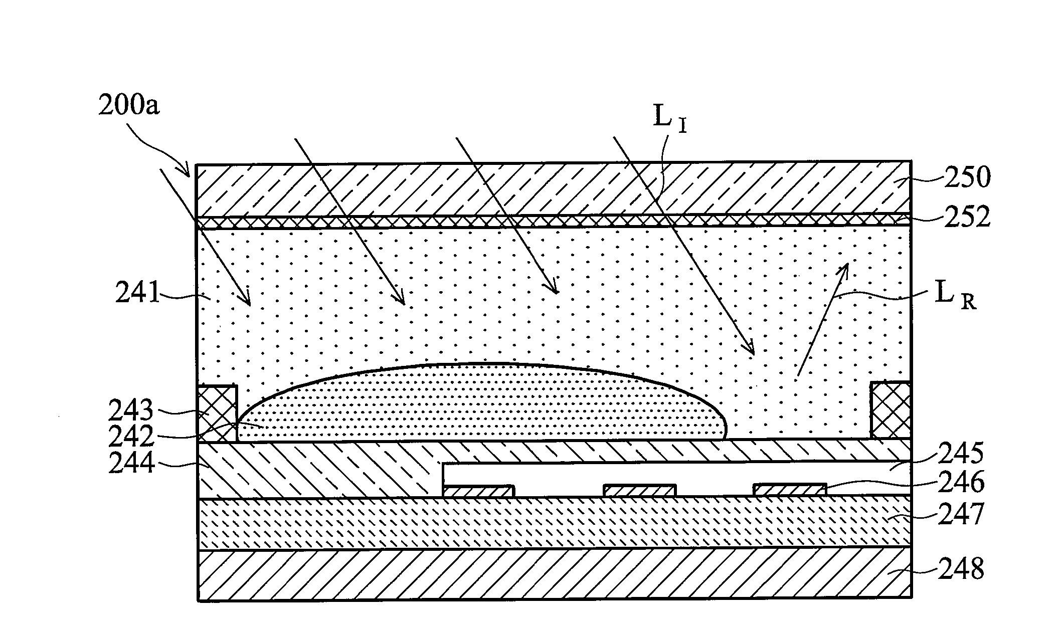
[0030]The invention are related to transflective electrowetting display devices. Patterned reflector structures are introduced and disposed on transmission regio...


PUM


Abstract

Electrowetting display devices are presented. The electrowetting display includes a first substrate and an opposing second substrate with a transparent polar fluid layer and an opaque non-polar fluid layer insoluble with each other and interposed between the first and second substrates. A first transparent electrode is disposed on the first substrate. A second transparent electrode is disposed on the second substrate. A dielectric layer is disposed on the second transparent electrode. A reflective plate structure is interposed between the second transparent electrode and the second substrate, thereby defining a reflective region and a transmission region. A backlight plate is disposed on the back of the second substrate. During operation, the opaque non-polar fluid converges, therefore, exposing equal areas of reflective region and transmission region.

Description

CROSS REFERENCE TO RELATED APPLICATIONS[0001]This application is based upon and claims the benefit of priority from a prior Taiwanese Patent Application No. 096138988, filed on Oct. 18, 2007, the entire contents of which are incorporated herein by reference.BACKGROUND OF THE INVENTION[0002]1. Field of the Invention[0003]The invention relates to display devices, and in particular to transflective electrowetting display devices.[0004]2. Description of the Related Art[0005]Electrowetting display devices are rendered images in accordance with electrowetting or electrocapillary. Briefly, the free surface energy of some fluids is changed due to electric field effects such that distribution area of the fluids can thus change along with the electric field effects.[0006]U.S. Pat. No. 6,967,763, the entirety of which is hereby incorporated by reference, discloses an electrowetting display device. An opaque non-polar fluid in the electrowetting display device converges due to electrowetting ef...

Claims


Application Information

Patent Timeline
IPC IPC(8): G02F1/17
CPCG02B26/004G02B26/005
Inventor CHENG, WEI-YUANHSIAO, CHIH-CHUNYANG, JEN-CHIENLO, KUO-LUNG
Owner IND TECH RES INST
Learn More