Key switch arrangement having an illuminating function

a technology of illuminating function and key switch, which is applied in the direction of contact mechanisms, emergency actuators, printing, etc., can solve the problems of increasing the overall height of the keyboard, difficult to mount the keyboard on a personal computer, and difficulty in substituting an illuminating type of keyboard for a normal, non-illuminating type of keyboard, etc., to achieve the effect of not increasing the height of the keyboard and not increasing the cos

Inactive Publication Date: 2009-04-23
OKI ELECTRIC IND CO LTD
View PDF12 Cites 87 Cited by
  • Summary
  • Abstract
  • Description
  • Claims
  • Application Information

AI Technical Summary

Benefits of technology

The present invention allows for an improved design without increasing the size or cost of the product. By placing the light source within the membrane sheet, it eliminates the necessity of added components such as lamps or batteries. This results in lower costs while maintaining efficient functionality.

Problems solved by technology

The technical problem addressed in this patent is how to create a keyboard that can be easily operated in low-light environments without adding extra space or increasing its overall height while maintaining excellent user experience.

Method used


Image

  • Key switch arrangement having an illuminating function
  • Key switch arrangement having an illuminating function
  • Key switch arrangement having an illuminating function

Examples


Embodiment Construction

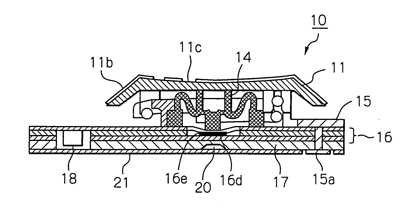
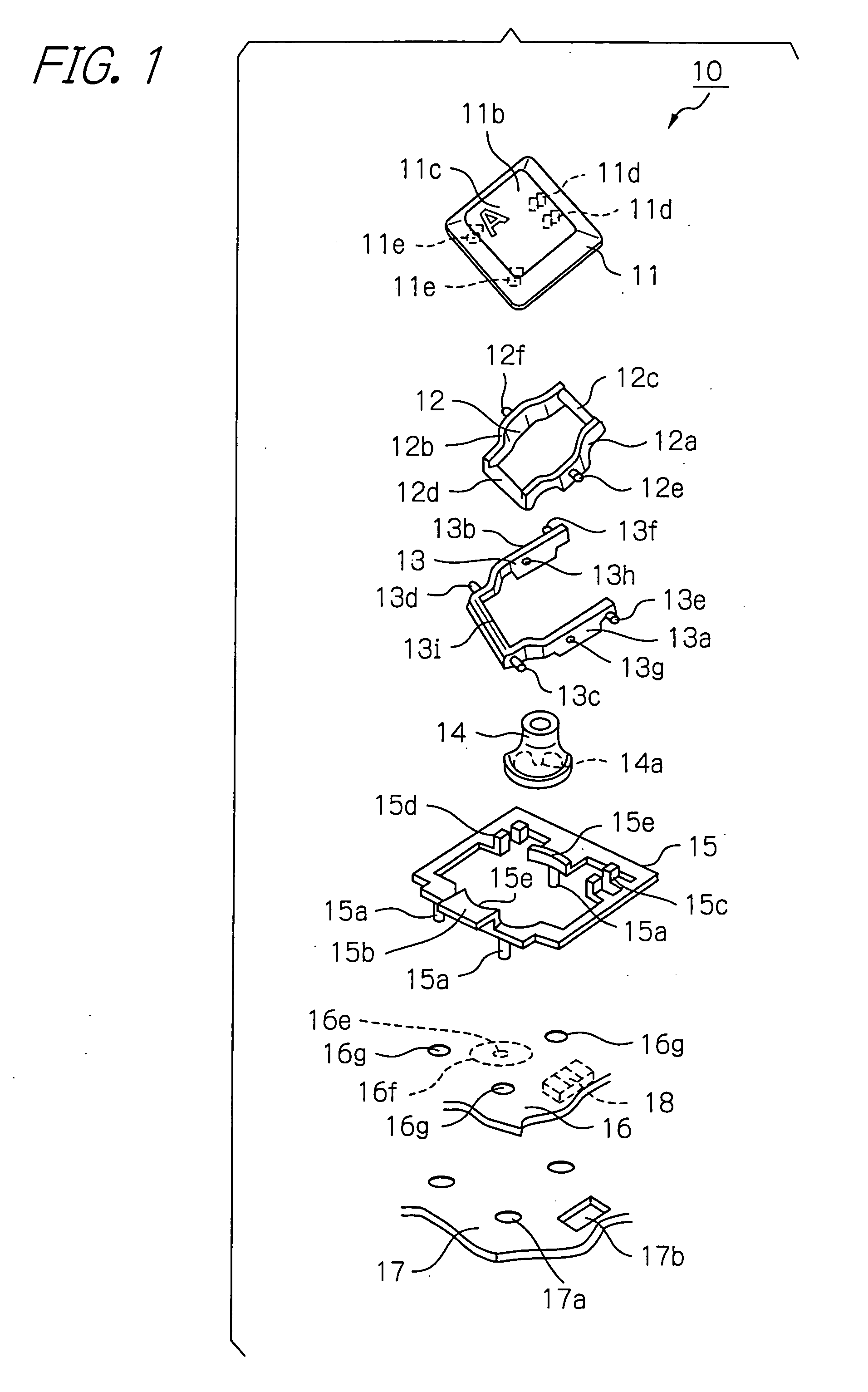
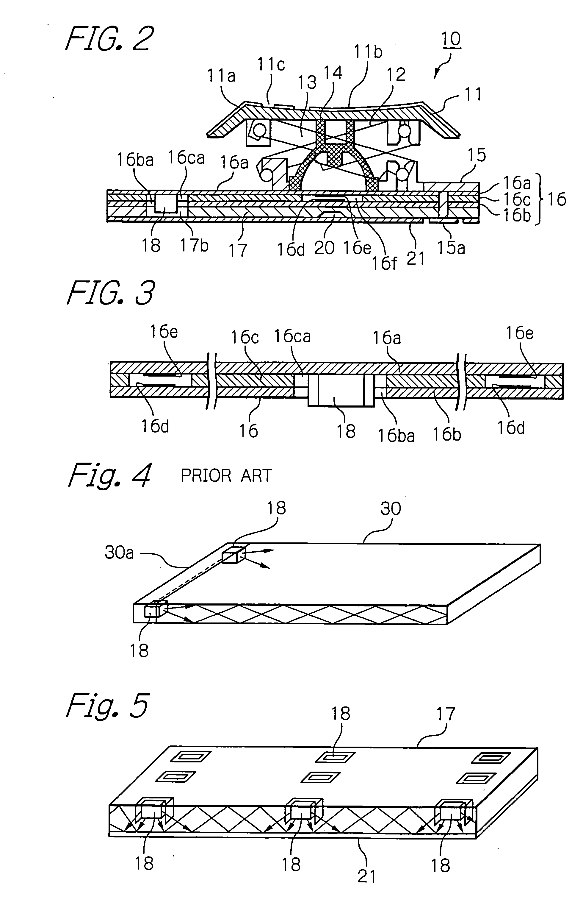
[0021]A preferred embodiment of a key switch arrangement in accordance with the present invention will be described reference to the accompanying drawings. FIG. 1 is an exploded perspective view schematically showing a key switch arrangement of an embodiment in accordance with the invention, and FIG. 2 is a cross-sectional view schematically showing the key switch arrangement of the embodiment. In FIG. 2, structural parts and elements like those shown in FIG. 1 are designated by the identical reference numerals, and will not be described repetitively in order to avoid redundancy.

[0022]In FIGS. 1 and 2, a key switch arrangement 10 in accordance with the embodiment includes a key-top 11, a first link member 12 rotatably mounted against the key-top 11, a second link member 13 mounted slidably against the key-top 11, a rubber dome 14 functioning as an elastic member to bend when the key-top is depressed and restore the key-top 11 to its original position when the depression force is rel...


PUM


Abstract

A key switch arrangement is able to accomplish the compatibility with a normal keyboard in respect of profile without increasing the height of the keyboard and reduce the cost without adding new members for a light source. The key switch arrangement includes a key-top having an optically transparent key-top having a cutout letter part formed thereon, an optically transparent membrane sheet having a contact, an optically transparent plate member arranged under the membrane sheet, and a light source arranged in the membrane sheet. The light source emits light to pass the plate member and the membrane sheet to illuminate the cutout letter part on the key-top.

Description


Claims


Application Information

Patent Timeline
Owner OKI ELECTRIC IND CO LTD
Why Eureka
Try Eureka