Variable compression ratio engine with isolated actuator

a variable compression ratio and actuator technology, applied in the direction of engines, mechanical equipment, machines/engines, etc., can solve the problems of mechanical damage to the engine, increase the heat transfer of the engine, and loss of engine operating efficiency, so as to prevent unintended spatial displacement of the piston and effect of effective altering the compression ratio

Inactive Publication Date: 2009-04-30
FORD GLOBAL TECH LLC
View PDF18 Cites 9 Cited by
  • Summary
  • Abstract
  • Description
  • Claims
  • Application Information

AI Technical Summary

Benefits of technology

[0010]The subject invention overcomes the disadvantages and shortcomings found in the prior art by providing a variable compression ratio piston and rod assembly for an internal combustion engine comprising a piston having a pin bore centered along a first axis, and a piston pin disposed in the pin bore. A connecting rod has a lower crank end and an upper piston end. The upper piston end includes a rod bore centered along a second axis that is offset from and parallel to the first axis of the pin bore. When operatively disposed in an internal combustion engine, the upper piston end of the connecting rod is subjected to a plurality of acceleration vectors including stroking acceleration vectors extending parallel to the cylinder bore axis, angular acceleration vectors centered around the first axis, and centrifugal acceleration vectors radiating from the first axis. An eccentric bushing pivotally interconnects the piston pin and the rod bore. The eccentric bushing includes a bore along the first axis that receives the piston pin and an eccentric outer journaled portion car

Problems solved by technology

Maximum combustion efficiency occurs at maximum combustion pressures, but in the absence of compression-induced autoignition that can create undesirable noise and also do mechanical damage to the engine.
For engines already operating at peak efficiency/maximum pressure, however, the added inlet pressures created by turbochargers and superchargers would over compress the combustion mixtures, thereby resulting in autoignition, often called knock due to the accompanying sound produced.
This ignition timing retard results in a loss of engine operating efficiency and also an increase of combustion heat transferred to

Method used


Image

  • Variable compression ratio engine with isolated actuator
  • Variable compression ratio engine with isolated actuator
  • Variable compression ratio engine with isolated actuator

Examples


Embodiment Construction

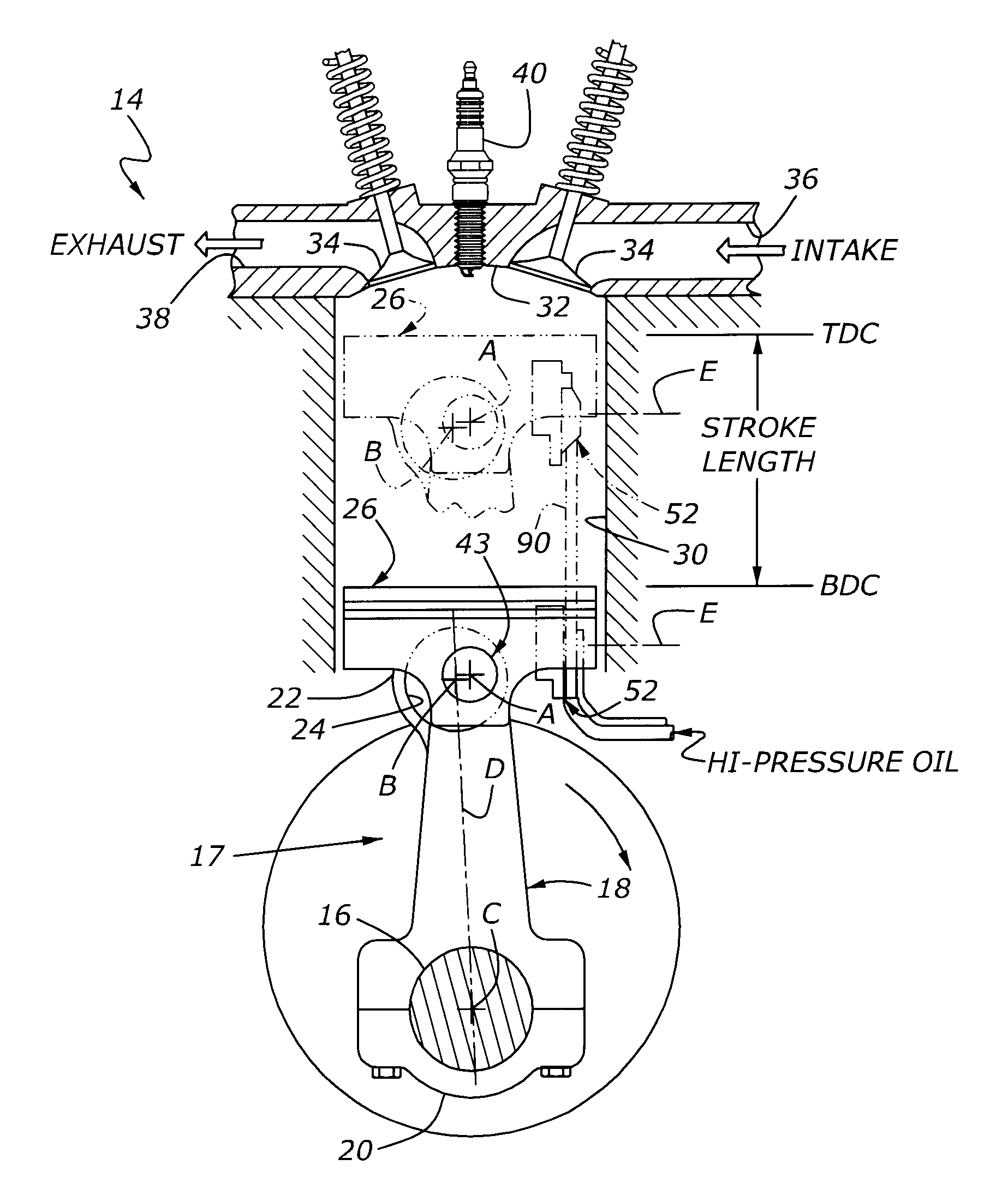
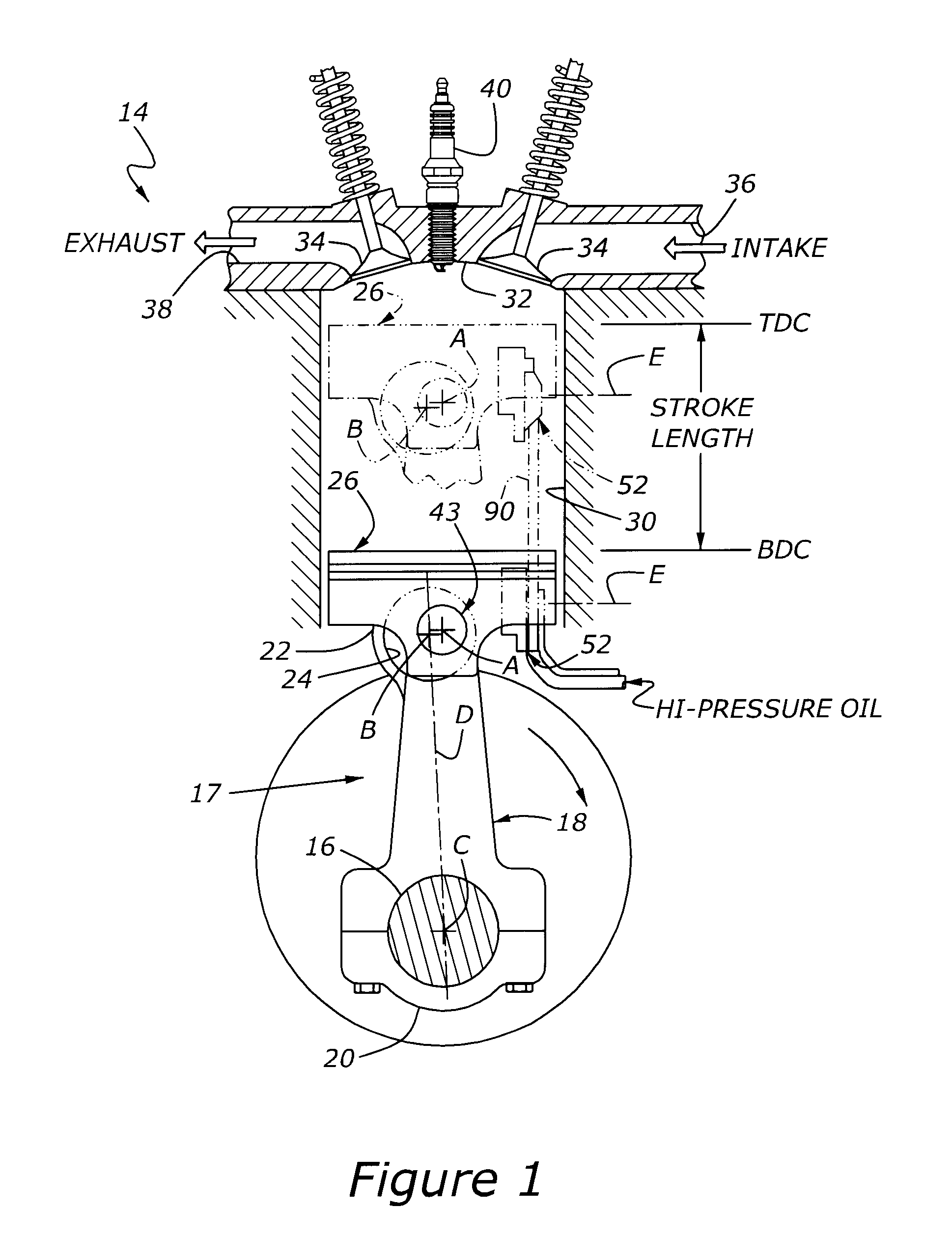
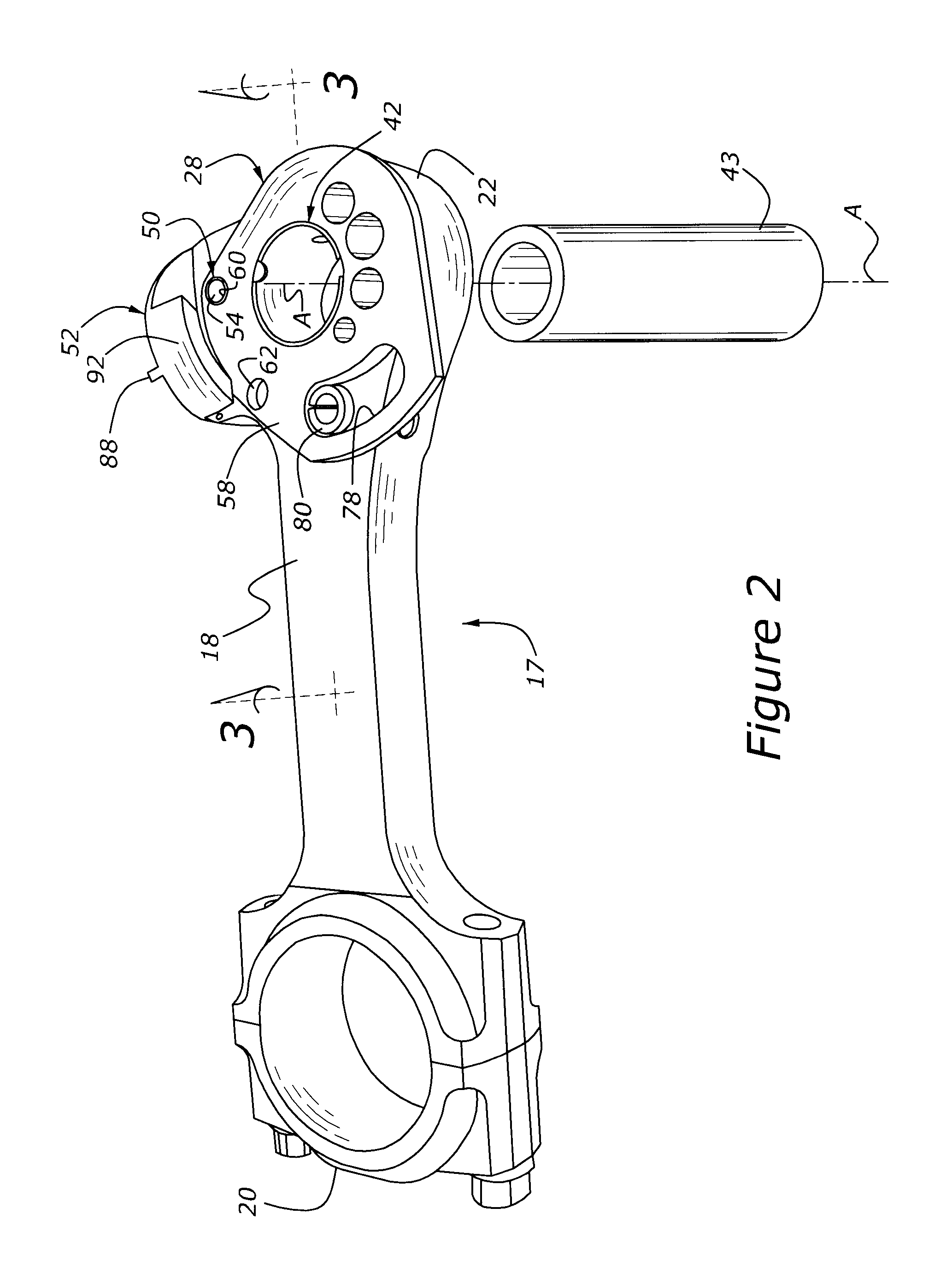
[0038]Referring to the Figures, a schematic of a gasoline powered, internal combustion engine is generally shown at 14 in FIG. 1. The engine 14 includes a crank shaft 16 supported for rotation in the typical main bearings (not shown). A connecting rod, generally indicated at 18, has a lower crank end 20 that is rotationally connected to the crank shaft 16, about a crank pin bore axis C. Longitudinally spaced from the crank end 20, the connecting rod 18 includes a piston end 22 supporting a rod bore 24 that is centered along a parallel axis B. A piston, generally indicated at 26, is pivotally connected to the piston end 22 of the connecting rod assembly 17 by a piston pin, generally indicated at 43. The piston pin 43 provides articulating, jointed movement of the piston 26 relative to the connecting rod assembly 17. The piston 26 is guided in a reciprocal stoking direction within a cylinder 30 for movement between Bottom Dead Center (BDC) and Top Dead Center (TDC) limits, the distanc...


PUM


Abstract

A variable compression ratio piston (26) and connecting rod (18) assembly for an internal combustion engine (14) includes an eccentric bushing (28) that carries a piston pin bushing (42) and contains a journaled portion (48) held in the rod bore (24) of the connecting rod (18). The eccentric bushing (28) can be selectively rotated between either of two angle adjusted positions to effect a change in the height of the piston (26) relative to the connecting rod (18), and thus change the compression ratio of the assembly. A latch (50) mechanism is actuated by oil jets (90, 91) external to the connecting rod (18). The latch (50) includes bolts (54, 56) with tapered tips that seat in oblong holes (60, 62) in a flange plate (58) to reduce destructive lash. A resilient stop post (80) bears the brunt of stresses associated with stopping the flange plate (58) during switching events to protect the latching bolts (54, 56).

Description

CROSS REFERENCE TO RELATED APPLICATIONS[0001]None.BACKGROUND OF THE INVENTION[0002]1. Field of the Invention[0003]The subject invention relates generally to a variable compression ratio engine in which the compression ratio in a cylinder for an internal combustion engine is adjusted while the engine is running, and more specifically toward an improved piston and connecting rod arrangement for dynamically varying the engine compression ratio.[0004]2. Related Art[0005]Gasoline engines have a limit on the maximum pressure that can be developed during the compression stroke. When the fuel / air mixture is subjected to pressure and temperature above a certain limit for a given period of time, it autoignites rather than burns. Maximum combustion efficiency occurs at maximum combustion pressures, but in the absence of compression-induced autoignition that can create undesirable noise and also do mechanical damage to the engine. When higher power outputs are desired for any given speed, more ...

Claims


Application Information

Patent Timeline
IPC IPC(8): F02B75/04
CPCF02B75/045
Inventor BERGER, ALVIN H.
Owner FORD GLOBAL TECH LLC
Why Eureka
Try Eureka