
Arrangement and method for controlling a combustion engine

a technology of combustion engine and arrangement and control method, which is applied in the direction of electric control, machines/engines, output power, etc., can solve the problems of increasing emissions, reducing the acid content of exhaust gases, and increasing the corresponding pressure, so as to achieve a large load range

Inactive Publication Date: 2006-10-12
SCANIA CV AB
View PDF3 Cites 4 Cited by
  • Summary
  • Abstract
  • Description
  • Claims
  • Application Information

AI Technical Summary

Benefits of technology

[0006] The object of the present invention is to provide an arrangement and a method for providing effective control of the self-ignition of a combustion engine of the kind mentioned in the introduction so that it can be used across a relatively large load range.
[0007] This object is achieved with the arrangement of the kind mentioned in the introduction which is characterised by the features indicated in the characterising part of claim 1. This involves applying, within a subrange, a strategy which entails the effective compression ratio in the cylinder being varied. By suitable variation of the compression ratio in the cylinder, self-ignition of fuel mixtures for different loads can be caused to take place at a substantially optimum crankshaft angle. This strategy may be applied in a subrange within which there are a lowest load at which an optimum compression ratio prevails and a highest load at which the effective compression ratio has been reduced to a minimum acceptable value. Such limitation to a minimum acceptable value is necessary in cases where reducing the effective compression ratio causes the lambda value to drop and hence the acid content of the exhaust gases to decrease. Lowering the lambda value results in corresponding pressure rises and increased emissions. At higher loads than this strategy caters for, the control unit applies a strategy which entails cooled exhaust gases being led to the combustion chamber. The cooled exhaust gases cause the ignition of the fuel mixture to take place later. This means that the control unit can raise the effective compression ratio in the cylinder and the lambda value, resulting in the possibility of more fuel being supplied to the fuel mixture in the combustion chamber, and in a higher engine load being achieved. This strategy is therefore applicable within a load range which is higher than and adjacent to the load range for the strategy which only entails the effective compression ratio in the cylinder being varied. The control unit applying different strategies within various mutually adjacent subranges makes it possible for self-ignition to be controlled towards an optimum crankshaft angle within a relatively large load range.
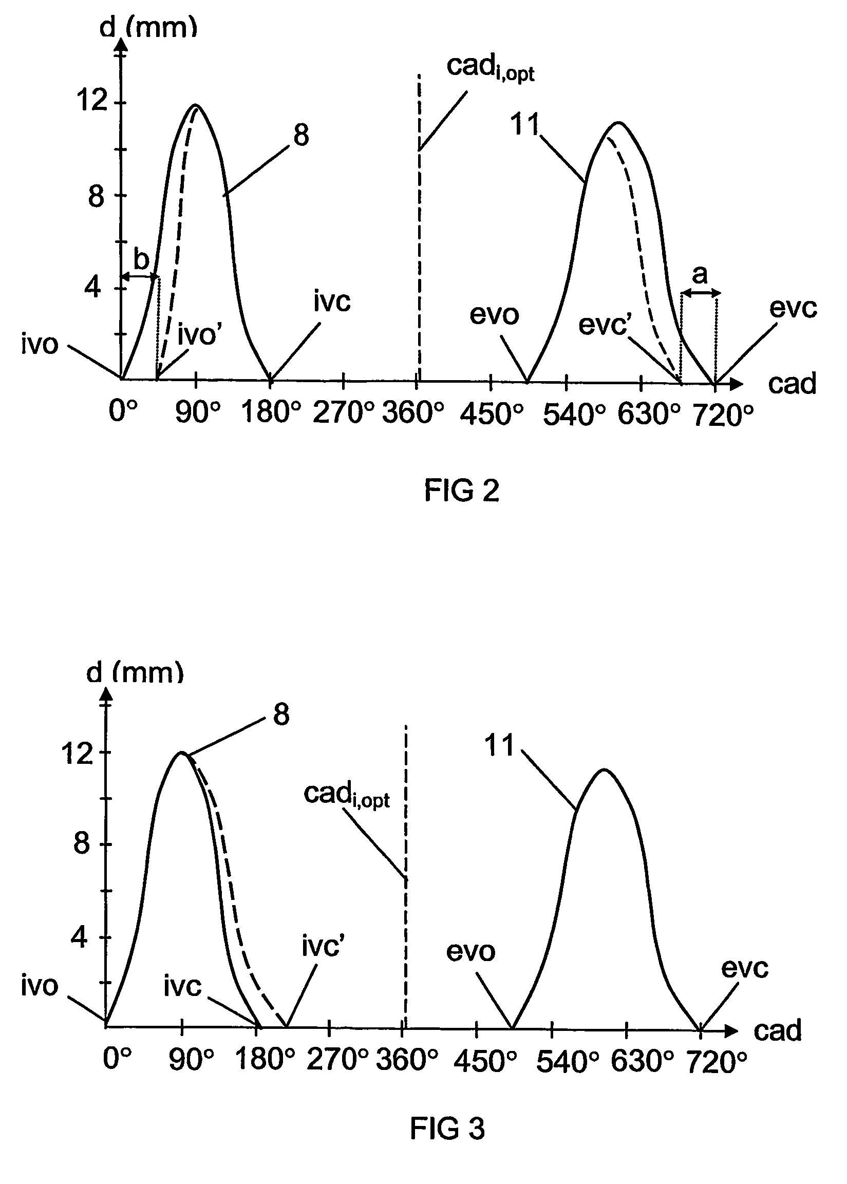
[0008] According to a preferred embodiment of the present invention, the control unit is adapted to regulating the effective compression ratio in the cylinder by initiating variable inlet valve closure. Inlet valve closure variation is an uncomplicated way of regulating the effective compression ratio. The later the inlet valve closes, the shorter the piston movement in the cylinder required for compressing the fuel mixture. With advantage, the arrangement comprises at least one hydraulic control system for lifting the inlet valve and the exhaust valve. Such hydraulic systems which quickly vary the inlet valve closure from one combustion process to another in response to control signals received from the control unit are conventionally available.
[0010] According to another preferred embodiment of the present invention, the arrangement comprises a first sensor for detecting a parameter which indicates the start of a combustion process in the combustion chamber, and a second sensor for estimating the crankshaft angle of the combustion engine, and the control unit is adapted to determining the crankshaft angle at the start of the combustion process. Said first sensor may be a pressure sensor which detects the pressure in the combustion chamber. The control unit can use information about the pressure characteristic in the combustion chamber for determining the crankshaft angle at which the self-ignition has taken place. The first sensor may alternatively be a sonic sensor or some other suitable sensor by which self-ignition in the combustion chamber can be detected. The second sensor may be a sensor which detects the rotational position of, for example, the engine's flywheel. The control unit is preferably adapted to comparing the actual crankshaft angle at the self-ignition of the combustion process with stored information concerning the optimum crankshaft angle for self-ignition of the combustion process and to using this information for controlling the self-ignition of the following combustion process. The control unit can calculate the difference between the actual crankshaft angle at self-ignition of the combustion process with stored information about the optimum crankshaft angle. Thereafter the control unit controls the lifting of the valves in such a way as to eliminate during the next combustion process any difference thus calculated.

Problems solved by technology

Such limitation to a minimum acceptable value is necessary in cases where reducing the effective compression ratio causes the lambda value to drop and hence the acid content of the exhaust gases to decrease.
Lowering the lambda value results in corresponding pressure rises and increased emissions.

Method used


Image

  • Arrangement and method for controlling a combustion engine
  • Arrangement and method for controlling a combustion engine
  • Arrangement and method for controlling a combustion engine

Examples


Embodiment Construction

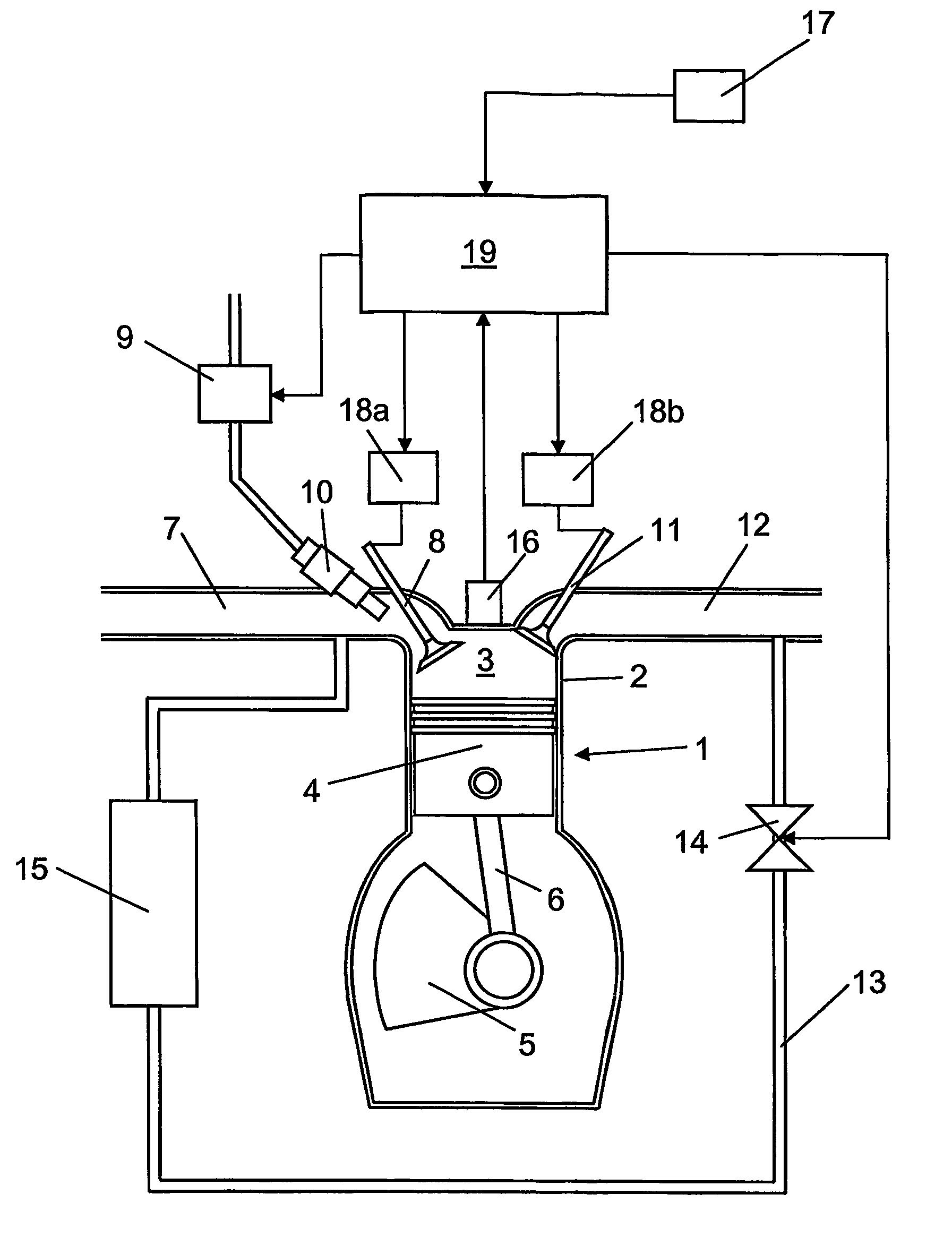
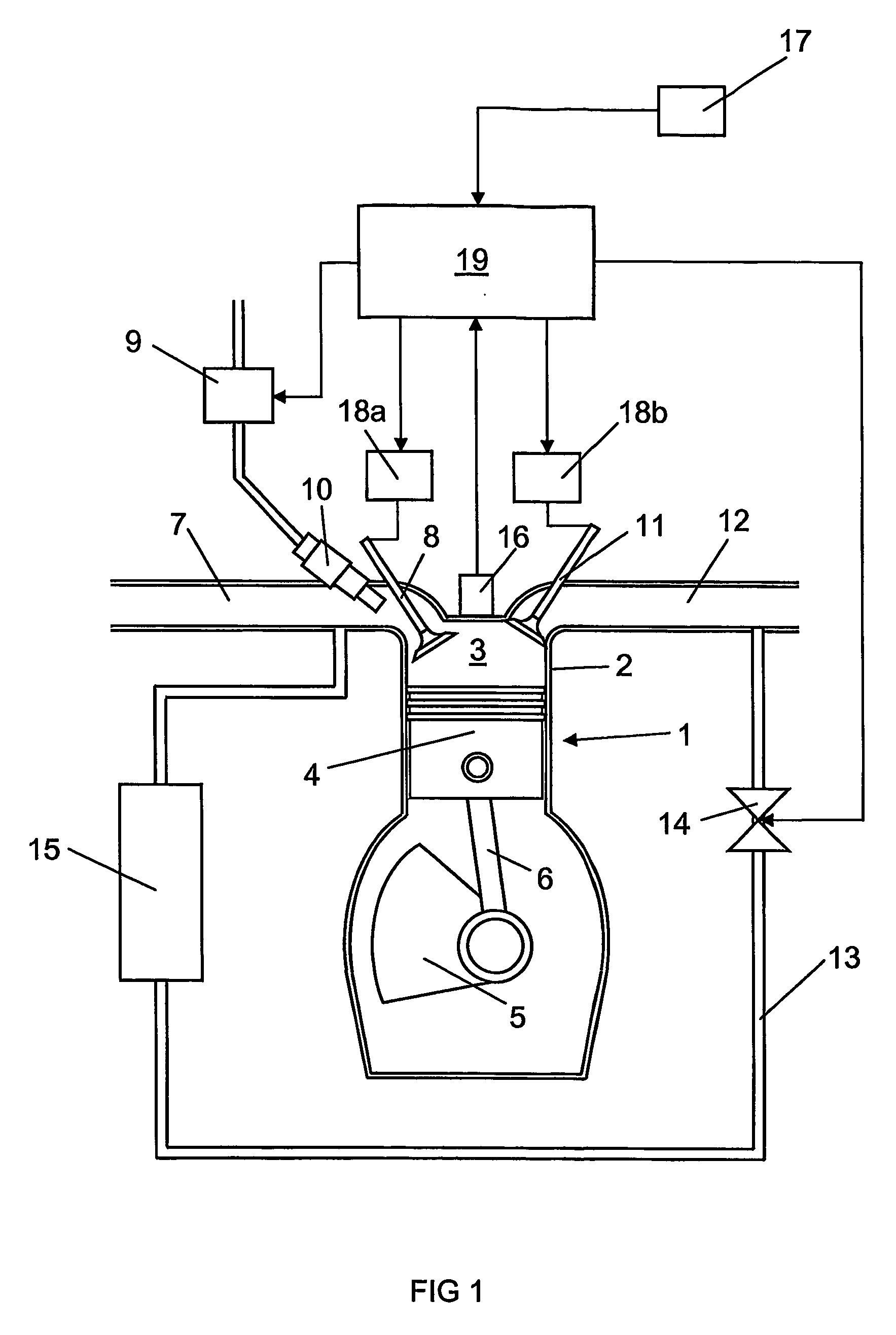
[0020]FIG. 1 depicts an arrangement for controlling a combustion engine 1 of the type in which a homogeneous mixture of fuel and air is compressed until self-ignition of the mixture takes place due to the heat arising during the compression. Such an engine 1 is usually called an HCCI (Homogeneous Charge Compression Ignition) engine. An HCCI engine may be regarded as a combination of an Otto engine and a diesel engine. A cylinder 2 of the engine 1 is depicted here. The engine 1 may of course have substantially any desired number of such cylinders 2. The engine 1 comprises a combustion chamber 3 which is bounded downwards in the cylinder 2 by a movable piston 4. The piston 4 is connected to a crankshaft 5 by a connecting rod 6. The movements of the piston 4 in the cylinder 2 are converted to rotary movement of the crankshaft 5.

[0021] When the piston 4 moves downwards in the cylinder 2 and an inlet valve 8 is open, air is drawn into the expanding combustion chamber 3 via an inlet line...


PUM


Abstract

An arrangement and a method for controlling a combustion engine, e.g. of the type called HCCI engine. A control unit is operable for controlling the self-ignition of the fuel mixture towards an optimum crankshaft angle (cadiopt) within a load range (Ltot). The load range (Ltot) can be divided into at least two subranges (LII, LIII). The control unit is operable to controlling the self-ignition of the fuel mixture towards an optimum crankshaft angle (cadiopt) within one of the subranges (LII) by a strategy (II) which entails the effective compression ratio (c) in the cylinder being varied, and within the second subrange (LIII) by another strategy (III) which entails a variable amount of cooled exhaust gases (ceg) being led to the combustion chamber also enabling in the second subrange (LIII) to control the self-ignition of the fuel mixture towards an optimum crankshaft angle (cadiopt) by variation of the effective compression ratio (c) in the cylinder without it falling below a lowest acceptable value {circle around (c)}min).

Description

BACKGROUND TO THE INVENTION, AND STATE OF THE ART [0001] The present invention relates to an arrangement and a method for controlling a combustion engine according to the preambles of claims 1 and 11. [0002] One type of such combustion engines are called HCCI (Homogeneous Charge Compression Ignition) engines and may be regarded as a combination of an Otto engine and a diesel engine. In HCCI engines, a homogeneous mixture of fuel and air is compressed in a combustion chamber until self-ignition of the fuel mixture takes place. Advantages of such engines are that they produce low discharges of nitrogen oxides NOx and soot particles while at the same time being of high efficiency. One reason for HCCI engines not being used conventionally to any great extent is that it is difficult to control the self-ignition of the fuel mixture to a correct crankshaft angle. [0003] Two different valve control strategies are known for controlling under laboratory conditions the self-ignition of the fue...

Claims


Application Information

Patent Timeline
IPC IPC(8): F02B1/12F02M25/07F02B3/00F02D13/02F02D15/04F02D41/30
CPCF02B1/12F02D13/0215F02D13/0265F02D13/0269F02D15/04Y02T10/142F02D35/028F02D41/3035F02D2041/001Y02T10/128F02D35/023Y02T10/12
Inventor LINDERYD, JOHANAGRELL, FREDRIK
Owner SCANIA CV AB
Learn More