Pressure sensor and method of manufacturing the same

a technology of pressure sensor and manufacturing method, which is applied in the direction of fluid pressure measurement, acceleration measurement using interia force, instruments, etc., can solve the problems of narrow detection range of load and inability to detect small loads, and achieve the effect of smooth change of resistan

Active Publication Date: 2012-11-13
MARUSAN NAME
View PDF3 Cites 4 Cited by
  • Summary
  • Abstract
  • Description
  • Claims
  • Application Information

AI Technical Summary

Benefits of technology

[0012]The present invention aims at providing a pressure sensor and a method of manufacturing the same, which can change the resistance to load smoothly in a relatively small load range and detect the pressure to the extent of relatively large load range.
[0016]Then, an increase in load deforms the substrate further, the area of contact between the above-mentioned resistor layer on non-conductive particles and the electrode layer increases gradually, and resistance changes smoothly.
[0017]When a larger load is applied and the substrate deforms further, not only the above-mentioned resistor layer (resistor layer projection) on the non-conductive particles but also the resistor layer (resistor layer recessed portion) between the non-conductive particles comes into contact with the electrode layer. As a result, it is possible to change resistance in a high load range and detect a wide range of loads.
[0026]Thus, since the resistor layer contains silicon resin, the resistor layer has flexibility. As a result, when the load is applied, the resistor layer between the non-conductive particles can deform and come into contact with the electrode layer gradually, resistance can be changed with respect to the large load, thus providing the wide range of load detection.
[0035]According to the present invention, it is possible to obtain the pressure sensor which allows the resistance to be changed smoothly in the relatively small load range and can detect the pressure in the relatively large load range. Further, according to the present invention, it is possible to obtain the method of manufacturing the pressure sensor.

Problems solved by technology

However, there is a problem that the whole surfaces of the electrode layer and the resistor layer are brought into contact by a relatively small load, and a range of detection of the loads is narrow.
On the other hand, in the case where relatively hard substrates are used as the first substrate and the second substrate, there is a problem that a small load does not deform the first substrate or the second substrate so that the small load cannot be detected.

Method used


Image

  • Pressure sensor and method of manufacturing the same
  • Pressure sensor and method of manufacturing the same
  • Pressure sensor and method of manufacturing the same

Examples


example 1

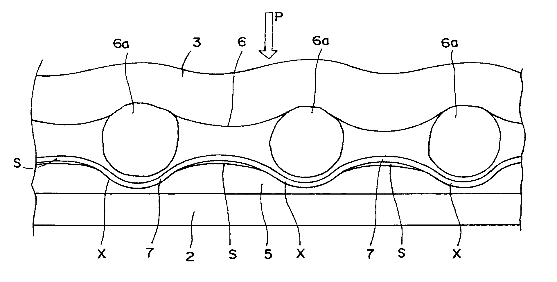
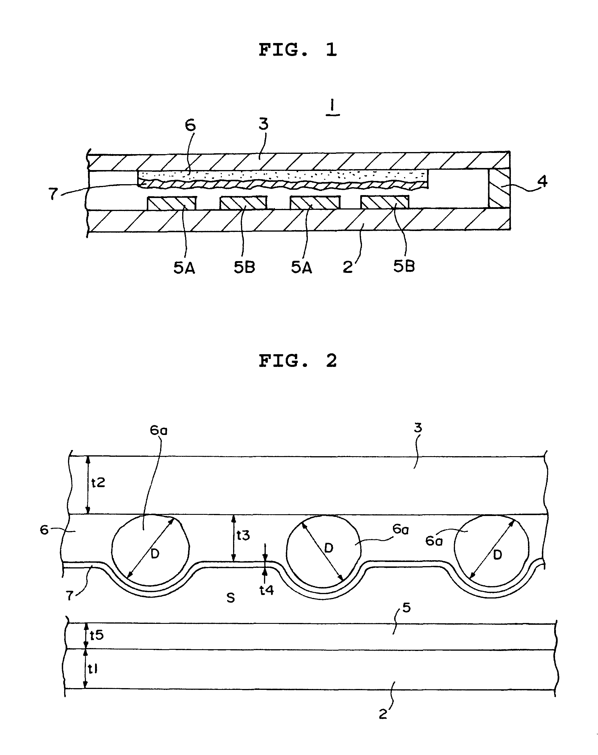
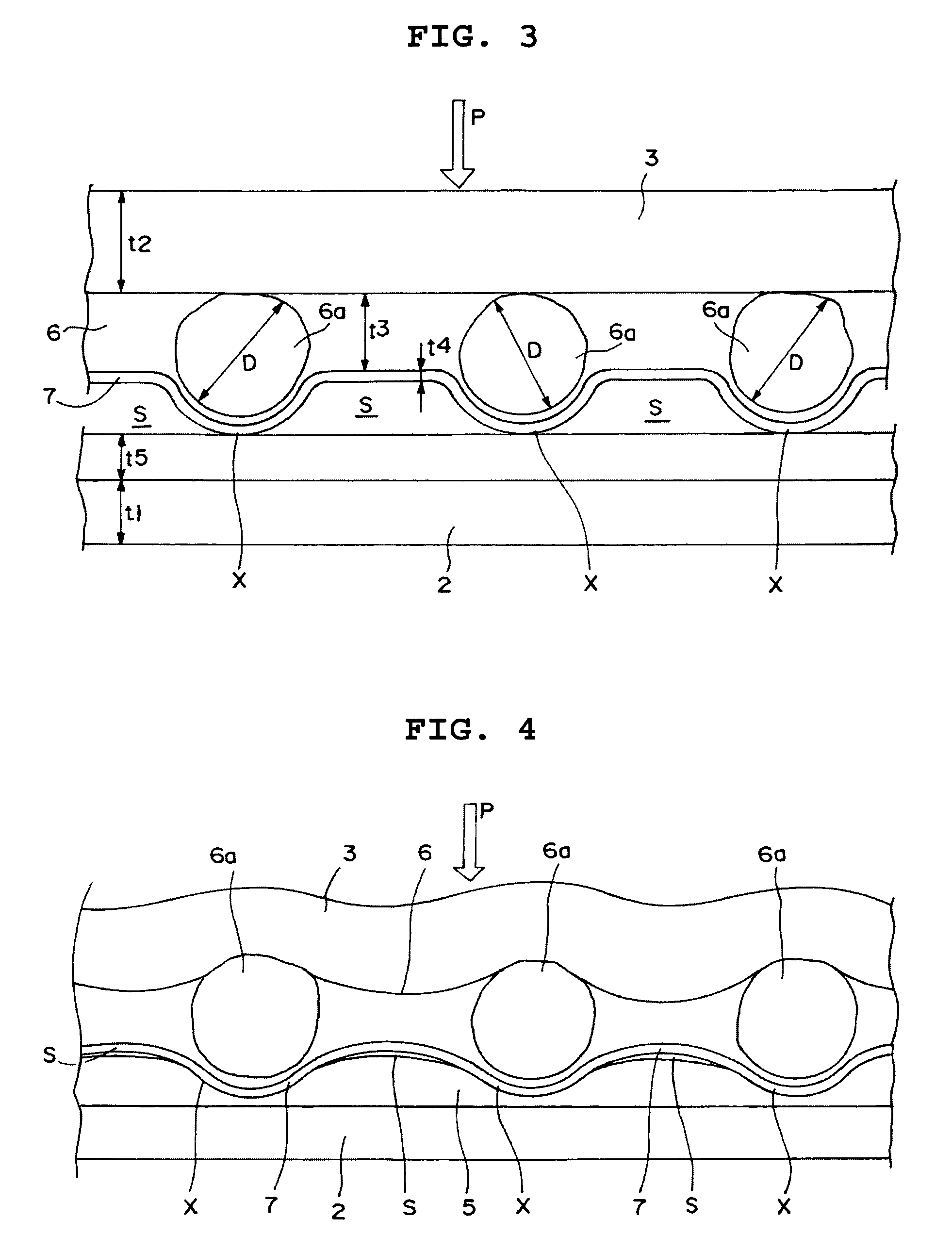
[0072]Using a 125 μm glass epoxy resin for a first substrate, a pair of electrodes (interdigital electrodes) made of copper were formed on a surface of the first substrate by etching. A thickness of the electrodes was set to 38 μm. Using a polyethylene terephthalate resin sheet with a thickness of 125 μm as a second substrate, an uneven layer 6 containing silicon dioxide particles was formed on a surface of the second substrate. The above-mentioned uneven layer 6 containing a polyester-based resin and 10% by weight of silicon dioxide particles with a particle diameter of 50 μm was formed to have a thickness of 20 μm.

[0073]Then, a resistor layer 7 was further formed on a surface of this uneven layer 6. A material of a phenol resin containing 5% by weight of silicon resin and 5% by weight of carbon powder was used for the resistor layer 7. A thickness of the resistor layer 7 was arranged to be 10 μm.

[0074]As for the thus formed pressure sensor, change in resistance to change in load w...


PUM


Abstract

The present invention provides a pressure sensor and a method of manufacturing the same, which can change resistance to load smoothly in a relatively small load range and detect the pressure to the extent of relatively large load range. An uneven layer 6 is formed of a resin containing non-conductive particles 6a and having insulation properties, on a surface of the second substrate 3, and a resistor layer 7 containing at least carbon powder and having a certain film thickness is formed on a surface of the uneven layer 6. A sum of a film thickness of the uneven layer 6 between the non-conductive particles 6a and a film thickness of the resistor layer 7 is smaller than a particle diameter of non-conductive particles 6a included in the uneven layer, and at least a resistor layer 7 is formed on the non-conductive particles 6a and between the non-conductive particles 6a.

Description

BACKGROUND OF THE INVENTION[0001]1. Field of the Invention[0002]The present invention relates to a pressure sensor which detects a change in load based on a change in resistance and a method of manufacturing the same.[0003]2. Description of the Related Art[0004]Generally, a pressure sensor 20 is provided with a first substrate 22 having formed thereon a pair of electrode layers 21A and 21B which are spaced apart and face each other, and a second substrate 24 having formed thereon a resistor layer 23 which comes into contact with the pair of electrode layers 21A and 21B to short-circuit the pair of electrode layers 21A and 21B as shown in FIGS. 6 to 8.[0005]The pressure sensor 20 is arranged so that an area of contact between the resistor layer 23 and the pair of electrode layers 21 may proportionally increase with increasing load P applied to at least one of the first and second substrates 22 and 24. Further, the resistor layer 23 of the pressure sensor 20 usually has a circular sha...

Claims


Application Information

Patent Timeline
Patent Type & Authority Patents(United States)
IPC IPC(8): H01L29/84
CPCG01L1/20H01C17/0652H01C17/06586
Inventor MORI, SEIJI
Owner MARUSAN NAME
Why Eureka
Try Eureka