Permanent magnet buried type electric motor

a permanent magnet and electric motor technology, applied in the direction of dynamo-electric machines, magnetic circuit rotating parts, magnetic circuit shapes/forms/construction, etc., can solve the problems of difficult to adjust the direction of magnetic flux and difficult to adjust the density distribution of magnetic flux

Active Publication Date: 2011-03-03
PANASONIC CORP
View PDF14 Cites 42 Cited by
  • Summary
  • Abstract
  • Description
  • Claims
  • Application Information

AI Technical Summary

Benefits of technology

[0012]In this configuration, near the intersection point of mutually adjacent arcs, a curvature of the outer circumferential curved surface of the rotor core changes smoothly, and a magnetic flux density distribution of the air gap part may be approximate to a sinusoidal wave shape.
[0013]In particular, when angle α is 0 degree, the mutually adjacent arcs are set in a relation such that the intersection point of the mutual arcs, a center of the arc at the d-axis side, and a center of the arc at the q-axis side are formed on a same straight line. Since the radius of the arc at the d-axis side is larger than the radius of the arc at the q-axis side, the curvature of the outer circumferential curved surface of the rotor core can be ideally changed smoothly, and the magnetic flux density distribution of the air gap part may be approximate to an ideal sinusoidal wave shape.

Problems solved by technology

It was hence difficult to adjust the direction of the magnetic flux in the arc portion, and also difficult to adjust the magnetic flux density distribution in the air gap part in a sinusoidal wave shape.

Method used


Image

  • Permanent magnet buried type electric motor
  • Permanent magnet buried type electric motor
  • Permanent magnet buried type electric motor

Examples


embodiment 1

Preferred Embodiment 1

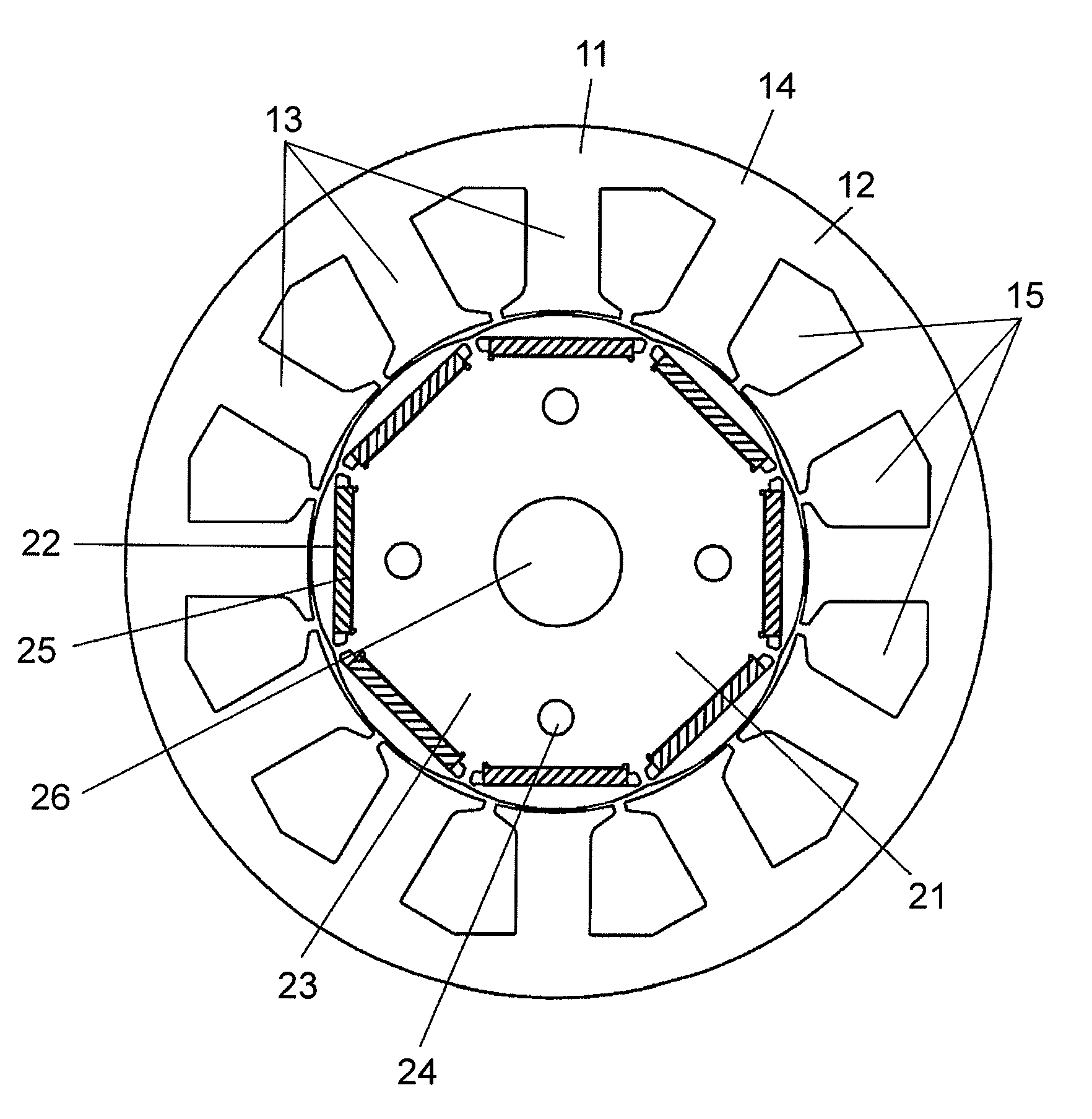
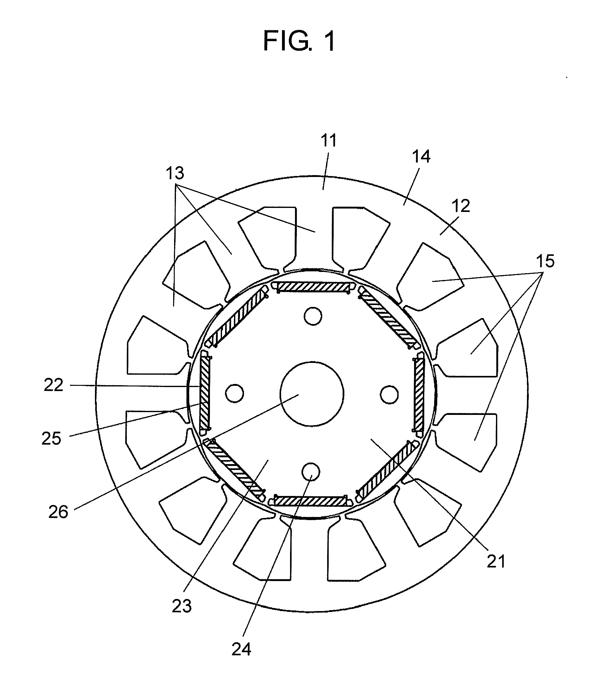
[0051]FIG. 1 is a sectional view of a permanent magnet buried type electric motor (or called an electric motor) in preferred embodiment 1 of the present invention.

[0052]The electric motor in preferred embodiment 1 has a configuration consisting of stator 11 and rotor 21.

[0053]Stator 11 includes stator core 14 laminated a plurality of high-permeability thin iron plates by pressing and blanking, and a winding (not shown) wound on stator core 14. This stator core 14 has yoke 12, a plurality of teeth 13 formed at the inner circumferential side of yoke 12, and slots 15 formed between adjacent teeth 13. A winding is wound on this stator core 14 by concentrated winding, and is accommodated in slots 15.

[0054]On the other hand, rotor 21 includes rotor core 23 forming a plurality of magnet burying holes 22, permanent magnets 25 to be buried in individual magnet burying holes 22, and end plates (not shown) disposed at both end parts in the axial direction. Rotor core 23 i...

embodiment 2

Preferred Embodiment 2

[0097]Preferred embodiment 2 of the present invention is explained below while referring to the accompanying drawings. Herein, same constituent elements as in preferred embodiment 1 are identified with same reference numerals, and the duplicate explanation is omitted.

[0098]FIG. 14 is a partially magnified view of the outer circumference corresponding to one magnetic pole in a rotor of a permanent magnet buried type electric motor in preferred embodiment 2 of the present invention.

[0099]The outer circumferential shape of rotor core 230 corresponding to one magnetic pole in the rotor of the electric motor of this preferred embodiment 2 is different from that of the rotor of the electric motor of preferred embodiment 1 in that it is composed of two arcs, arc B1 at the d-axis side and arc B2 at the q-axis side, having different radii R3, R4.

[0100]Arc B1 positioned at the intersection point of d-axis and outer circumference of rotor core 230 is formed at radius R3 c...

embodiment 3

Preferred Embodiment 3

[0106]Preferred embodiment 3 of the present invention is explained below while referring to the accompanying drawings. Herein, same constituent elements as in preferred embodiment 1 are identified with same reference numerals, and the duplicate explanation is omitted.

[0107]FIG. 15 is a partially magnified view of the outer circumference corresponding to one magnetic pole in a rotor of a permanent magnet buried type electric motor in preferred embodiment 3 of the present invention.

[0108]The outer circumferential shape of rotor core 240 corresponding to one magnetic pole in the rotor of the electric motor of this preferred embodiment 3 is different from that of the rotor of the electric motor of preferred embodiment 1 in that it is composed of two arcs, arc C1 at the d-axis side and arc C2 at the q-axis side, having different radii R5, R6.

[0109]Arc C1 positioned at the intersection point of d-axis and outer circumference of rotor core 240 is formed at radius R5 c...


PUM


Abstract

Supposing a straight line joining rotation center O of a rotor and a magnetic pole middle, that is, a middle of permanent magnets (25) to be a d-axis, and a straight line joining rotation center O and an intermediate point of mutually adjacent permanent magnets (25) to be a q-axis, mutually adjacent arcs A1 and A2 are composed such that radius R1 of arc A1 at the d-axis side is larger than radius R2 of arc A2 at the q-axis side, and that, at intersection point β of mutual arcs A1 and A2, angle α of tangent u of arc A2 at the q-axis side with respect to tangent t of arc A1 at the d-axis side is set by −3 degrees≦α≦2 degrees.

Description

TECHNICAL FIELD[0001]The present invention relates to a permanent magnet buried type electric motor including a stator having a winding wound on a stator core composed of teeth and a yoke, and a rotor rotatably held opposite to an inner circumference of the teeth, and having a rotor core with a permanent magnet buried in a magnet burying hole.BACKGROUND ART[0002]In this technical field, technologies disclosed in patent document 1 and patent document 2 are known.[0003]In the invention disclosed in patent document 1, permanent magnet burying holes are provided at equal intervals for the number of magnetic poles in a rotor in the circumferential direction of a rotor core. In each permanent magnet burying hole, a permanent magnet is held, and each permanent magnet is disposed so that the magnetic pole surface different from an adjacent permanent magnet may form a magnetic pole part directed to the outer circumferential direction of the iron core. The outer circumferential curved surface...

Claims


Application Information

Patent Timeline
Patent Type & Authority Applications(United States)
IPC IPC(8): H02K1/27
CPCH02K1/276H02K2213/03H02K29/03H02K21/16H02K1/22H02K1/27H02K21/24
Inventor LI, HUYOSHIKAWA, YUICHIMURAKAMI, HIROSHISATO, HIROKI
Owner PANASONIC CORP
Why Eureka
Try Eureka