Control system for internal combustion engine

a control system and internal combustion engine technology, applied in the direction of electric control, machines/engines, mechanical equipment, etc., can solve the problems of limiting the range of air-fuel ratio detectable by the oxygen concentration sensor, egr system itself suffers from delay in operation, and increase the deviation of oxygen concentration, so as to achieve optimal control of fuel injection

Active Publication Date: 2006-01-19
HONDA MOTOR CO LTD
View PDF3 Cites 44 Cited by
  • Summary
  • Abstract
  • Description
  • Claims
  • Application Information

AI Technical Summary

Benefits of technology

[0012] It is a first object of the present invention to provide a control system for an internal combustion engine, which is capable of optimally controlling fuel injection by an injector even in a transient state of the engine.
[0013] It is a second object of the present invention to provide a control system for an internal combustion engine, which is capable of properly controlling an injector that injects fuel into a cylinder during switching of an air-fuel ratio, to thereby suppress torque variation.
[0014] It is a third object of the present invention to provide a control system for an internal combustion engine, which is capable of smoothly changing a fuel injection control mode in accordance with an increase or a decrease in load on the engine to suppress excessive switching of the control mode performed in response to a slight change in the load on the engine, and torque variation caused by the switching of the control mode.

Problems solved by technology

However, there is a limit to the range of the air-fuel ratio detectable by the oxygen concentration sensor.
Furthermore, the exhaust manifold having the oxygen concentration sensor inserted therein is distant from the cylinders, which produces a time lag before the EGR gases from the exhaust manifold are actually supplied to the cylinders, and the EGR system itself suffers from delay in operation.
Further, in the diesel engine, the EGR gas amount is set to a very large value compared with the gasoline engine, and hence the amount of change in the EGR gas amount in the transient state is also large, which causes an increased deviation in the oxygen concentration.
This makes it impossible for the control system to properly estimate the amount of air in the EGR gases and the total amount of air supplied to the cylinders, which causes the fuel injection amount to deviate from an appropriate value, thereby making it impossible to accurately control the air-fuel ratio to the target air-fuel ratio.
Therefore, the system suffers from the problem that it causes engine output torque variation during switching of the air-fuel ratio.
However, the Publication of Japanese Patent No. 3116876 does not disclose a method of controlling fuel injection during an increase in the load on the engine, or during transition from a high-load operating condition of the engine to a low-load operating condition thereof under which the low-temperature combustion is possible.

Method used


Image

  • Control system for internal combustion engine
  • Control system for internal combustion engine
  • Control system for internal combustion engine

Examples


Embodiment Construction

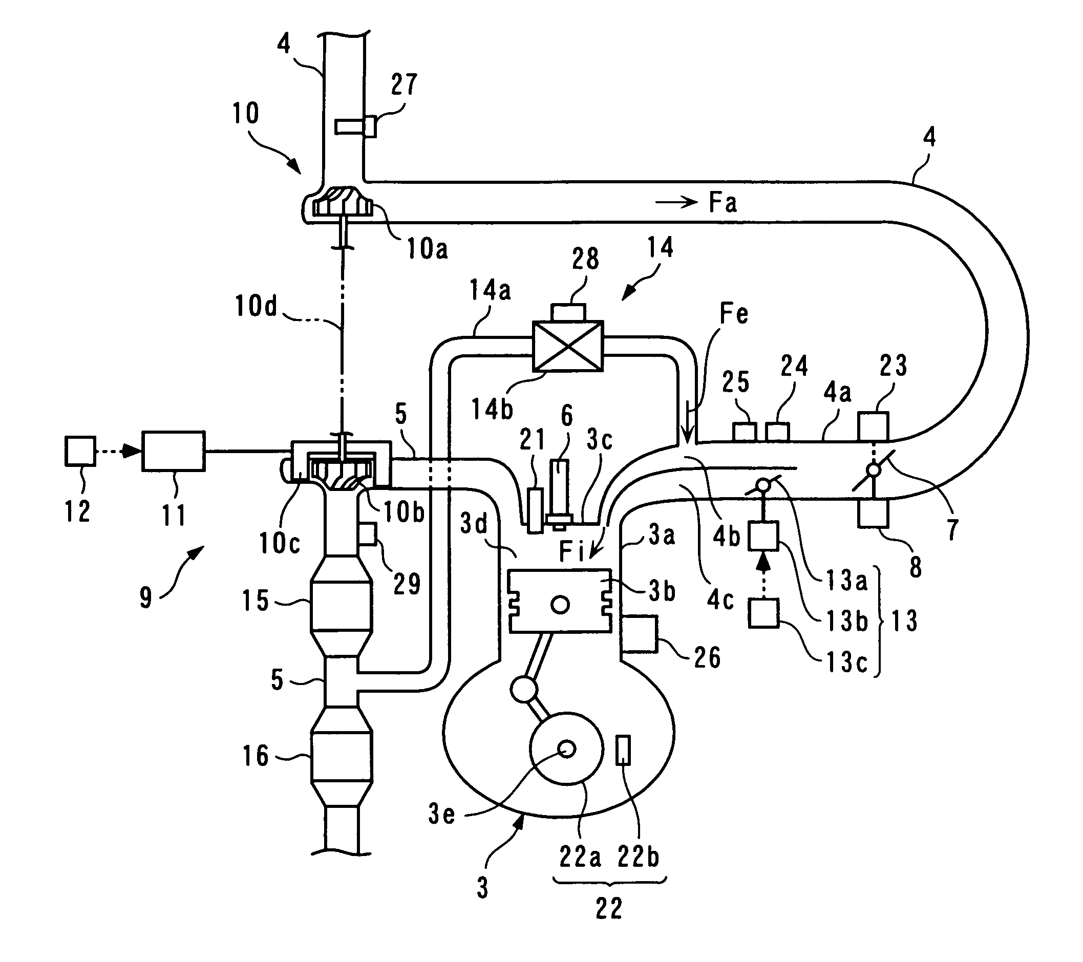
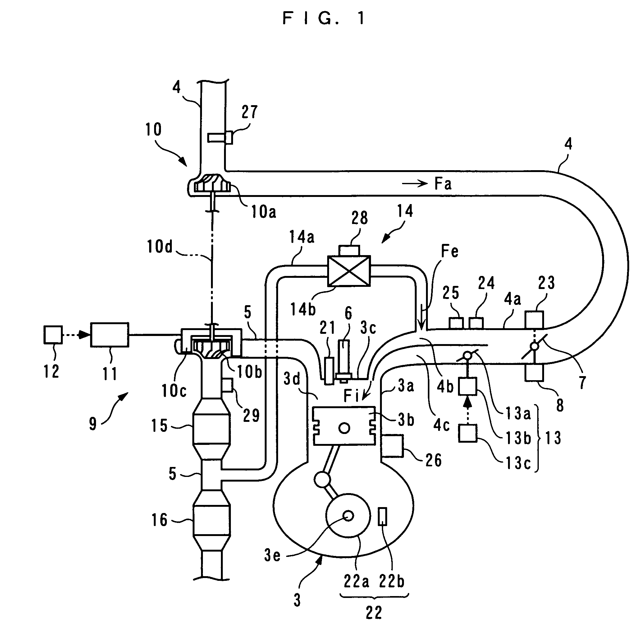
[0090] The invention will now be described in detail with reference to the drawings showing embodiments thereof. An internal combustion engine (hereinafter simply referred to as “the engine”) 3 shown in FIG. 1, to which is applied a control system according to a first embodiment of the present invention, is a diesel engine having e.g. four cylinders (only one of which is shown), and installed on an automotive vehicle (not shown). Defined between a piston 3b and a cylinder head 3c of each cylinder 3a is a combustion chamber 3d. To the combustion chamber 3d are connected an intake pipe 4 (intake system) and an exhaust pipe 5, and an intake valve and an exhaust valve (neither of which is shown) are arranged in an intake port of the intake pipe 4 and an exhaust port of the exhaust pipe 5, respectively. Further, a fuel injection valve (hereinafter referred to as “the injector”) 6 and an in-cylinder pressure sensor 21 are mounted through the cylinder head 3c in a manner facing the combust...


PUM


Abstract

A control system for an internal combustion engine, which is capable of optimally controlling fuel injection by an injector even in a transient state of the engine. An ECU 2 of the engine provided with an EGR system (14) controls the amount (Fa) of air drawn into cylinders (3a) via an intake system (4). An air flow sensor (27) detects the intake air amount (Fa). The ECU 2 estimates a flow rate (Fe_hat) of EGR gases according to response delay of recirculation of the EGR gases by the EGR system (14), estimates the amount (mo2) of oxygen existing in the cylinder (3a), based on the detected intake air amount (Fa) and the estimated flow rate (Fe_hat) of the EGR gases, determines a fuel injection parameter (Q*) based on the engine speed (Ne) and the estimated in-cylinder oxygen amount (mo2), and controls an injector (6) based on the determined fuel injection parameter (Q*).

Description

BACKGROUND OF THE INVENTION [0001] 1. Field of the Invention [0002] This invention relates to a control system for an internal combustion engine provided with an exhaust recirculation (EGR) system for recirculating part of exhaust gases to an intake system, and more particularly to a control system of the type that performs control of fuel injection by an injector, etc. [0003] 2. Description of the Related Art [0004] Conventionally, a control system of this kind has been proposed in Japanese Laid-Open Patent Publication (Kokai) No. H08-61112. In the control system, the amount Ga of intake air drawn into cylinders is detected by an air flow sensor. Further, the total amount Gf of gases to be supplied to the cylinders is mapped in advance using the stepped-on amount of an accelerator pedal and the rotational speed of the engine as parameters, and the total amount Gf is calculated by searching the map according to the parameters detected during operation of the engine. Furthermore, the...

Claims


Application Information

Patent Timeline
Patent Type & Authority Applications(United States)
IPC IPC(8): F02D41/14
CPCF01N3/0814F01N13/009F01N2570/10F01N2570/12F02B37/00F02B37/24F02D41/0007F02D41/0072F02D41/1458F02D41/187F02D2041/0015F02D2200/0402F02M25/071F02M25/0718F02M25/0722F02M25/0723F02M25/0756Y02T10/144Y02T10/47F01N3/0842F02M26/07F02M26/15F02M26/19F02M26/20F02M26/48Y02T10/12Y02T10/40
Inventor SASAKI, SHIZUOWANG, JUNMINNEELY, GARY D.
Owner HONDA MOTOR CO LTD
Why Eureka
Try Eureka