Omnidirectional spherical roller caster

a spherical roller caster and caster technology, applied in the direction of roller skates, skateboards, sport apparatus, etc., can solve the problems of jerky, inconvenient initial movement of the load, energy-intensive initial motion of the load, etc., and achieve the initial improper alignment of the heavy load on the caster to the desired direction of movement. , the loss of energy, and the inability to accurately adjust the load

Inactive Publication Date: 2002-06-13
COSTA RONALD D JR +1
View PDF0 Cites 41 Cited by
  • Summary
  • Abstract
  • Description
  • Claims
  • Application Information

AI Technical Summary

Benefits of technology

0033] Another object of this invention is to provide transport systems of sim

Problems solved by technology

This swinging motion is typically at a much greater frictional loss than rolling, thus causing loss of energy.
This resistance can cause jerky, spasmodic, imprecise, and energy intensive initial motion of the load.
In other words, it is hard to get a stationary heavy load supported on casters initially improperly aligned to the desired direction of movement to commence movement in the desired direction, let alone to smoothly do so.
However, the exposed rolling surface of the sphere may pick up such contamination from the surfaces, normally a floor, over and on which rolling is performed as does, when later rolled into the supportive cavity, cause increased frictional resistance.
The problem is that such a structure simply moves the frictional scrubbing an misalignment problem to another, lower, level, dictating that even the spherical ball roller caster will at least initially present a higher rolling resistance in some directions than in others.
Unfortunately, the predominant part of world has no snow, or has long periods without snow.
Common paired-wheel roller skates, known and manufactured for many years, can move either forward or backward only in a straight line, but these roller skates cannot rotate and spin like figure skates.
Additionally, because of this wheel arrangement, it is difficult for a roller skater to lean left or right, in order to pivot or negotiate tight curves.
Conventional in-line skates having single in-line wheels simulate the feel and motion of ice skating, but do not achieve the apparently free movement of figure ice skates.
However, because the wheels are mounted on horizontal shafts, the roller blades cannot rotate and spin like ice skates.
These combinations are not desired from the standpoint of too much friction or too little control.
The configuration of this skate mechanism is very complex and cumbersome, costly to manufacture and repair, and control in other applications is doubtful.
While advances such as urethane wheels, kicktails, laminated wood decks, precision bearings, griptape and concave decks have offered better control, they have not changed the motion characteristics, relying instead on straining riders' athletic ability to squeeze new performance limits from existing equipment.
This is a very difficult and dangerous maneuver, requiring high speed-generated momentum to overcome friction

Method used


Image

  • Omnidirectional spherical roller caster
  • Omnidirectional spherical roller caster
  • Omnidirectional spherical roller caster

Examples


example two

B. EXAMPLE TWO

OMNIDIRECTIONAL SKATEBOARD

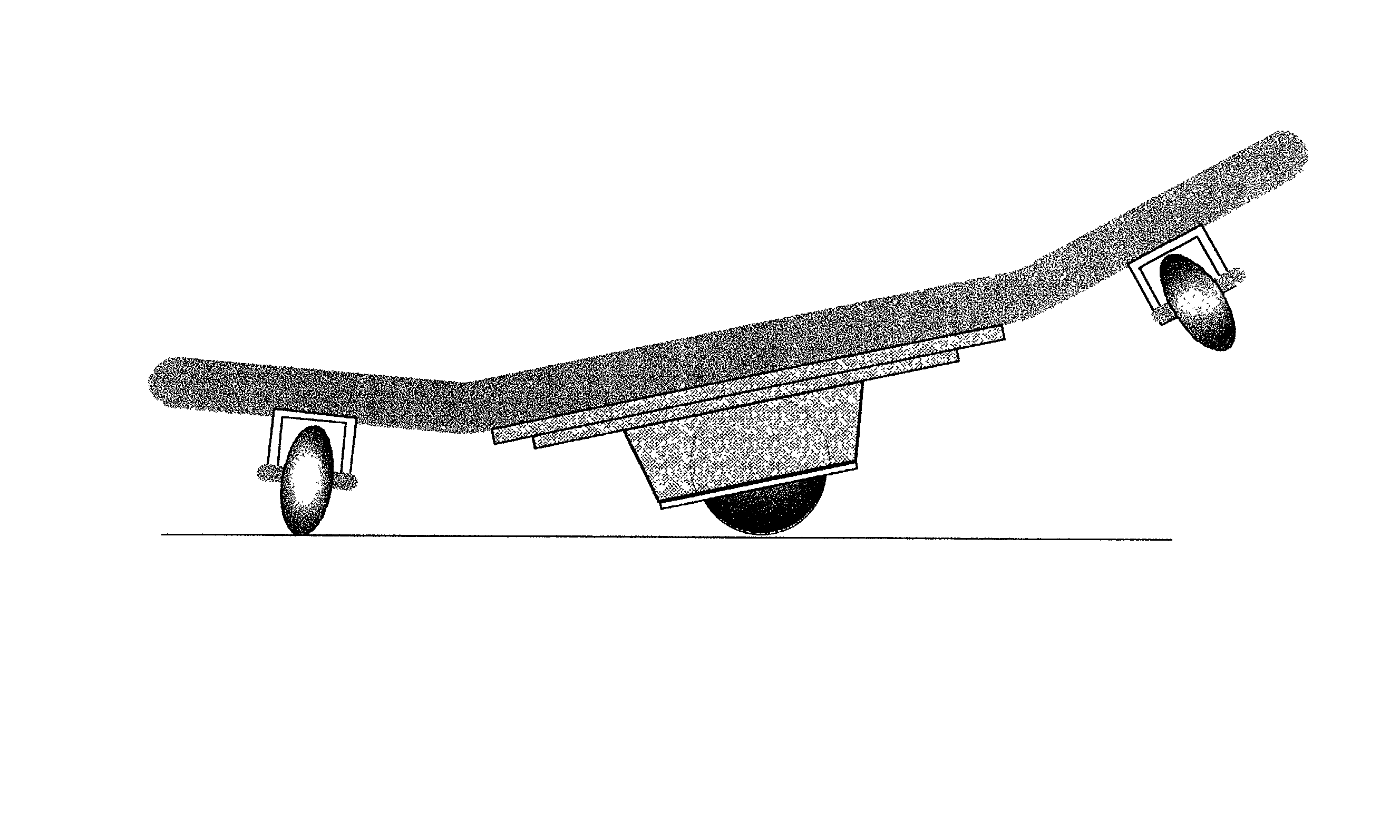
[0081] Another particularly preferred and more specialized embodiment of this invention is an omnidirectional skateboard shown in FIG. 5. This board comprises an integral, elongated, structurally rigid, single-piece, formed platform for supporting a skater. The platform has a central longitudinal axis along the length of the board, with a flat central portion 50 and bilateral, upwardly inclining wings 51 extending laterally from the center portion. Unlike a conventional skateboard, this invention does not require identification of fore and aft portions, as it is equally effective whatever end the user chooses to go forward. This allows a monumental increase in freedom of movement.

[0082] This skateboard has one or more longitudinally spaced spherical roller assemblies 60, as described hereinbefore, centrally attached to the underside of the flat central portion 50 of the platform structure. Each assembly housing 56 contains at least one spheric...

example three

C. EXAMPLE THREE

OMNIDIRECTIONAL PLATFORM

[0096] Another important and highly preferred embodiment of this invention is an omnidirectional platform, such as one appending a conveyor system. This platform may contain a plurality of attached housings as shown in FIG. 9, each having one or more concave spherical cavities. Attachment to a platform may be as illustrated in FIG. 2, 3, or screwed in as in FIG. 11. As described before, each cavity has an annular opening; however, in this case the opening is on the upper side of the housing (i.e., the housing is inverted), to form one or more spherical socket capable of containing a spherical roller 9. Such a platform can have as many spherical roller assemblies as is required, and in various configurations. A linear grid configuration is shown in FIG. 9.

[0097] As before, there is a plurality of cylindrical bores equidistantly geometrically disposed on the lower surface of the spherical socket, opposite the topside annular opening. There is a ...


PUM


Abstract

A caster capable of omnidirectional transport having a spherical roller freely mounted within a housing having a concave spherical cavity. A plurality of cylindrical bores is disposed perpendicular to the inner concave surface in equilateral geometric configuration, axially converging toward the center of the cavity. A plurality of small internal caster assemblies, mounted for free independent rotation about the convergent axis, extend from within the bores to contact the spherical roller, thereby creating a loading surface capable of providing omnidirectional rotation. The spherical roller interfaces between the loading surface of the cavity and a surface onto which the entire caster assembly is imparted omnidirectional movement.

Description

[0001] 1. Field of the Invention[0002] The present invention relates generally to caster / roller systems, and is more particularly is directed toward a new and improved spherical roller caster system advantageous for omnidirectional movement over and against surfaces.[0003] 2. Description of Related Art[0004] 2.1 Casters and Rollers[0005] Casters are very ancient, and rollers even more so, possibly even preceding the wheel. Rollers support unidirectional rolling movement. Casters support ominidirectional rolling movement, but at a price. Once aligned in the desired direction of movement, a caster presents but little rolling resistance, and essentially serves as a roller or wheel. However, if a caster is not properly aligned for rolling movement in a new direction then the caster must "swing around" its pivot axis until the correct rolling alignment is assumed. This swinging motion involves a slipping and a sliding, as opposed to a rolling, of the wheel of the caster. This swinging mo...

Claims


Application Information

Patent Timeline
IPC IPC(8): A63C17/01A63C17/04A63C17/24
CPCA63C17/004A63C17/24A63C17/014A63C17/01
Inventor COSTA, RONALD D. JR.RORABAUGH, DALE
Owner COSTA RONALD D JR
Why Eureka
Try Eureka