Light-emitting device, illuminating apparatus, and display apparatus

a technology of light-emitting devices and illuminating devices, which is applied in the direction of semiconductor devices for light sources, lighting and heating devices, instruments, etc., can solve the problems of affecting the use of backlight units, affecting the appearance of display panels, and inevitably increasing the size of the bezel portion of the display panel, so as to reduce the quantity of light, reduce the profile, and facilitate the change of light quantity at the corners

Inactive Publication Date: 2015-08-13
SHARP KK
View PDF2 Cites 41 Cited by
  • Summary
  • Abstract
  • Description
  • Claims
  • Application Information

AI Technical Summary

Benefits of technology

[0045]According to the invention, the reflective member includes the second reflecting member disposed so as to extend from each corner of the first reflecting member while being inclined with respect to the light-emitting portion, and thus, since the second reflecting member can reflect light in a direction toward the illumination object (display panel), it is possible to suppress a decrease in the quantity of light applied to the display panel via the corner of the first reflecting member. As a result, the display panel can be irradiated with light with uniformity in light intensity in the planar direction, and also the light-emitting device can be made lower in profile.
[0046]Moreover, according to the invention, light emitted from the light-emitting portion, at least partly, reaches the base portion of the reflective member disposed around the light-emitting portion, and part of the light which has reached the base portion is reflected from the flat-shaped base portion so as to be applied to the illumination object. Since the light reflected from the base portion travels diffusely, it is possible to apply a sufficient quantity of light not only to that region of the illumination object which faces the light-emitting portion, but also to vicinal regions thereof. Moreover, the other part of the light which has reached the base portion is reflected from the base portion for its travel toward the inclined portion, and is then reflected from the flat-shaped inclined portion so as to be applied to the illumination object. Accordingly, in the illumination object, not only the regions facing the light-emitting portion and the base portion, but also a vicinal region facing the inclined portion can be irradiated with a sufficient quantity of light. Furthermore, since the angle of inclination of the surface of the second reflecting member with respect to the surface of the base portion is smaller than the angle of inclination of the surface of the inclined portion with respect to the surface of the base portion, it follows that a larger quantity of light can be reflected in a direction toward the illumination object via the corners. Hence, the light-emitting device of the invention is capable of applying light to the illumination object with uniformity in brightness in the planar direction.
[0047]Moreover, according to the invention, since the second reflecting member has a triangle shape when viewed in a plan view in the optical-axis direction of the light-emitting portion from the illumination object, it is possible to cause changes in light quantity smoothly at the corners.
[0048]Moreover, according to the invention, since one side of the triangular second reflecting member is connected to the surface of the base portion, it follows that the distances between the center of the light-emitting portion and the individual sides are substantially the same, wherefore the second reflecting member portions are irradiated with substantially the same quantity of light, with consequent attainment of uniformity in light quantity at the corners. Moreover, since a point of intersection of the other two sides of the triangular second reflecting member is connected to a point of intersection of two adjacent sides of the polygonal first reflecting member, it follows that the inclined second reflecting member extends up to the intersection point of the polygon for distribution of light throughout the corner, which makes it possible to avoid that the corner will be brought into a low-light condition.
[0049]Moreover, according to the invention, since the arc-like parts of the second reflecting member portions are equidistant from the center of the light-emitting portion, it follows that the second reflecting member portions are irradiated with the same quantity of light, with consequent attainment of uniformity in light quantity at the corners.
[0050]Moreover, according to the invention, since the distance in the optical-axis direction between the part of the inclined portion which lies farthest from the surface of the base portion in the optical-axis direction and the surface of the base portion is shorter than the distance in the optical-axis direction between the part of the optical member which lies farthest from the surface of the base portion in the optical-axis direction and the surface of the base portion. In other words, the illumination object-sided end of the inclined portion lies farther away than the illumination object-sided end of the optical member with respect to the illumination object. This makes it possible to facilitate irradiation of light to the illumination object-sided end, namely, the vertex of the inclined portion, and thereby suppress a decrease in the quantity of light applied to a part of the illumination object which faces the vertex, wherefore even greater uniformity in brightness can be ensured in the illumination object in its planar direction.

Problems solved by technology

Although the LED has excellent characteristics, including lower power consumption, longer service life, and the capability of reduction in environmental burdens without the use of mercury, its use as a light source for a backlight unit has fallen behind because of its expensiveness, the fact that there had been no white-color LED prior to the invention of a blue-color LED, and its high directivity.
However, the edge-lighting type backlight unit poses the following problems: localized arrangement of light sources at the edge portion of the light guide plate results in concentration of heat generated by the light sources; and the size of the bezel portion of the display panel is inevitably increased.
Furthermore, the edge-lighting type backlight unit is subjected to severe restrictions in terms of local dimming control which attracts attention as a control technique capable of display of high-quality images and energy saving, and is therefore incapable of split-region control that achieves production of high-quality displayed images and low power consumption as well.

Method used


Image

  • Light-emitting device, illuminating apparatus, and display apparatus
  • Light-emitting device, illuminating apparatus, and display apparatus
  • Light-emitting device, illuminating apparatus, and display apparatus

Examples


first embodiment

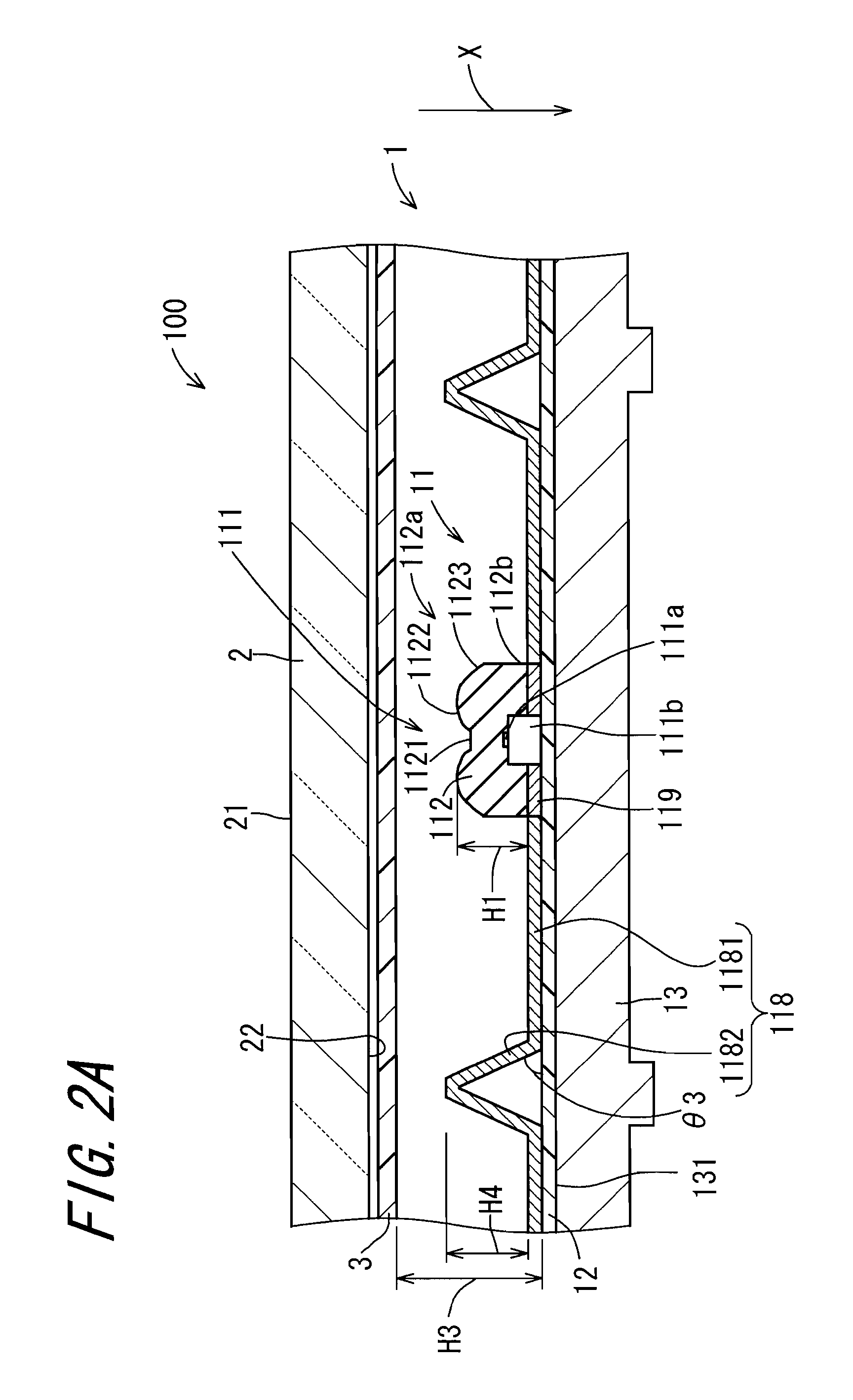
[0139]Next, the invention will be described. Except that a reflective member 113 as will hereafter be described is provided instead of the first reflective member 118, based on the basic structure thus far described, this embodiment is structurally identical with the above-described basic structure, wherefore the components that play the same or corresponding roles as in the basic structure will be identified with the same reference symbols, and the descriptions thereof will be omitted.

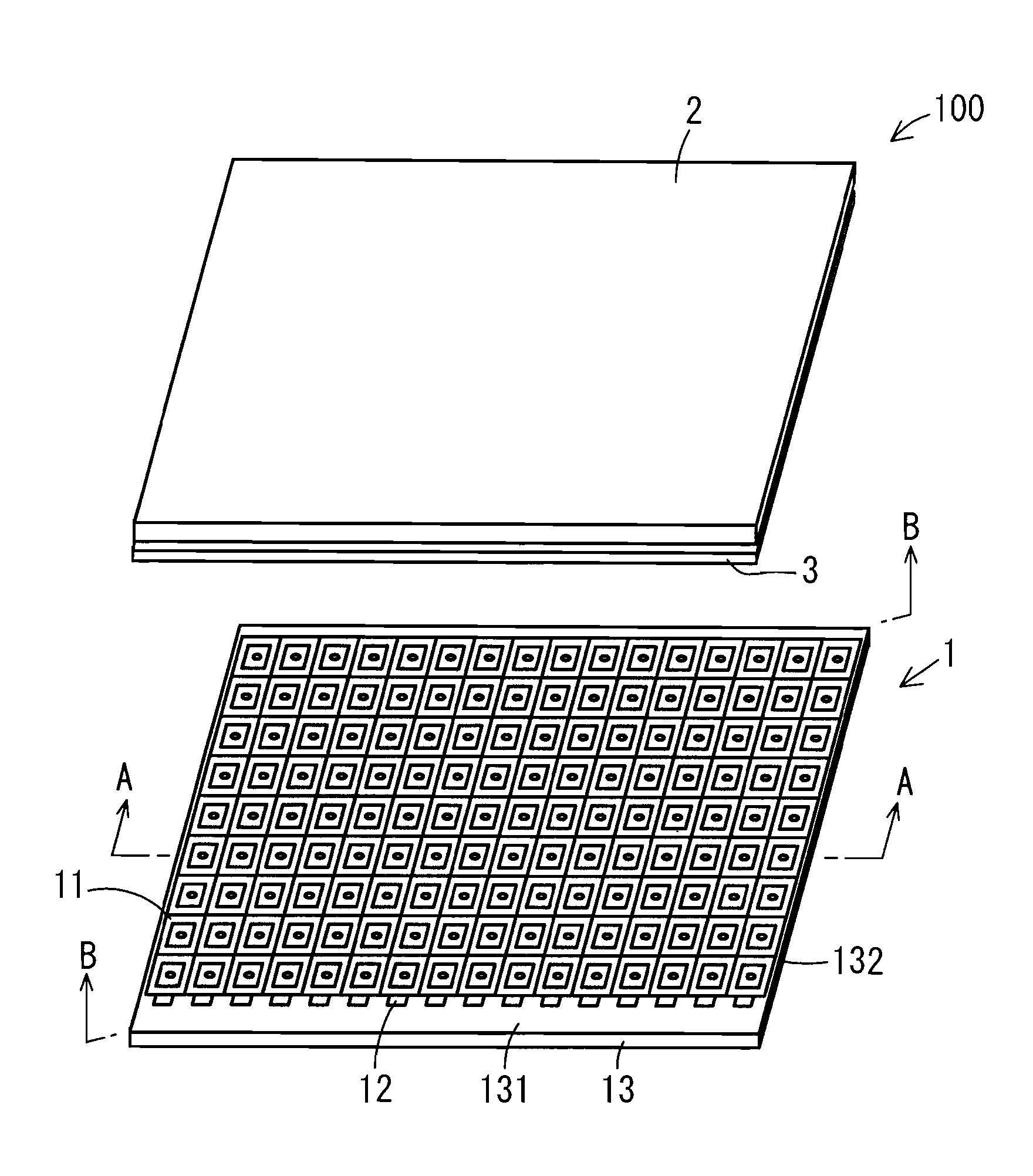
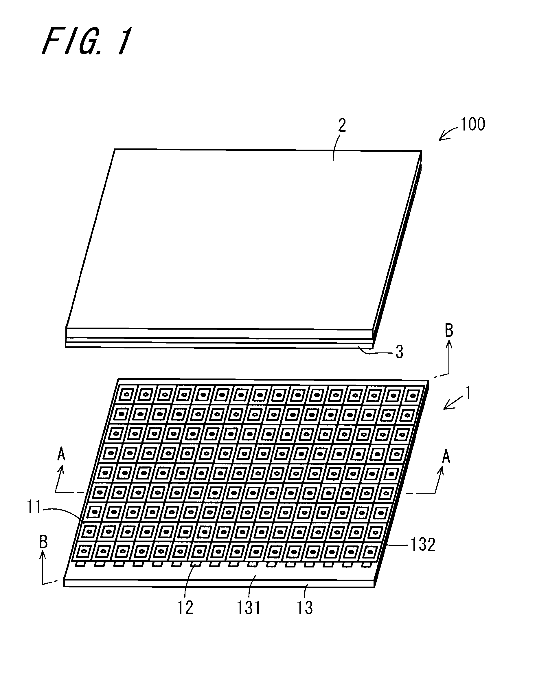
[0140]FIG. 7A is a view schematically showing the section of the liquid-crystal display apparatus 100 in accordance with the first embodiment of the invention taken along the line A-A of FIG. 1. FIG. 7B is a view schematically showing the section of the liquid-crystal display apparatus 100 in accordance with the first embodiment of the invention taken along the line B-B of FIG. 1. FIG. 8A is a perspective view of the reflective member 113, and FIG. 9A is a view showing the reflective member 113 as vie...

second embodiment

[0173]As shown in FIG. 15, the first step is to dispose the reflecting sheet 116 extending in the direction Y on the printed circuit board 12, on which a plurality of LED chips 111a each supported by the base support 111b are arranged in the direction Y, so as to surround each of the LED chips 111a. Next, the second step is to cover each of the LED chips 111a by the lens 112 on the reflecting sheet 116. Then, the third step is to dispose the first reflecting member 115 which comprises the first reflecting portion 1151 surrounding the reflecting sheet 116 and the second reflecting portion 1152 surrounding the first reflecting portion 1151, and also includes the second reflecting member 1132 placed on the first reflecting portion 1151. The assembly of the backlight unit of the second embodiment according to the above-described process steps is conducive to more efficient production of backlight units.


PUM


Abstract

The invention provides a light-emitting device for use in a backlight unit of a display apparatus including a display panel, which is capable of applying light to an illumination object with uniformity in brightness in the planar direction of the illumination object and can be made lower in profile, as well as an illuminating apparatus and a display apparatus including the light-emitting device. A backlight unit (1) is provided with a printed circuit board (12), a plurality of light-emitting portions (111) disposed on the printed circuit board (12) and having a base support (111b), an LED chip (111a) and a lens (112), and a reflective member (118) disposed around each light-emitting portion (111) and having a first reflecting member (1131) and a second reflecting member (1132).

Description

TECHNICAL FIELD[0001]The present invention relates to a light-emitting device which is disposed in a backlight unit for applying light to the back side of a display panel, and, an illuminating apparatus and a display apparatus including the light-emitting device.BACKGROUND ART[0002]In a display panel in which a liquid crystal is sealed in between two transparent substrates, upon application of voltage, the orientations of liquid crystal molecules are changed with consequent variations in light transmittance, so that a predetermined image or the like is displayed in an optical manner. In the display panel, since the liquid crystal does not emit light by itself as a light emitter, for example, a transmissive liquid crystal panel has, at its back side, a backlight unit for effecting irradiation of light from a light source such as a cold-cathode tube (CCFL) or a light-emitting diode (LED).[0003]Backlight units are classified into two categories, namely a direct-lighting type in which l...

Claims


Application Information

Patent Timeline
Patent Type & Authority Applications(United States)
IPC IPC(8): F21V7/04
CPCF21V7/04G02F1/133611H01L33/58H01L33/60G02F1/133603G02F1/133605G02F1/133612G02F1/133607H01L33/54H01L2224/48091H01L2924/1815H01L2924/00014F21K9/20H01L33/483F21Y2115/10
Inventor WADA, TAKASUMIONO, YASUHIROMASUDA, MAKOTOOHKUBO, KENZOSHIRAI, NOBUHIRO
Owner SHARP KK
Why Eureka
Try Eureka