Arrangement and method for controlling a combustion engine

a technology of combustion engine and crankshaft, which is applied in the direction of electric control, machines/engines, output power, etc., can solve the problem of fuel mixture self-ignition at a premature crankshaft angle, and achieve the effect of large load rang

Inactive Publication Date: 2007-08-28
SCANIA CV AB
View PDF6 Cites 3 Cited by
  • Summary
  • Abstract
  • Description
  • Claims
  • Application Information

AI Technical Summary

Benefits of technology

[0007]The object of the present invention is to provide an arrangement and a method for providing effective control of the self-ignition of a combustion engine of the kind mentioned in the introduction so that it can be used across a relatively large load range.
[0009]According to a preferred embodiment of the present invention, the control unit is adapted, within the first subrange, to initiating exhaust valve closure and inlet valve opening in such a way that a variable amount of hot exhaust gases from a combustion process is retained in the combustion chamber. Exhaust gases can be retained in the combustion chamber by closing the exhaust valve earlier than in the case of conventional exhaust valve closure. Later opening of the inlet valve is also necessary if the pressure of the exhaust gases retained is to be reduced to a level such that they do not leave the combustion chamber when the inlet valve opens. With advantage, the control unit is adapted, within the first subrange, to initiating inlet valve closure in such a way as to result in an optimum effective compression ratio in the cylinder. This means that an optimum effective compression ratio in the cylinder can be used throughout the first subrange. At the same time, the effective compression ratio within the second subrange can be reduced from an optimum level.
[0010]According to another preferred embodiment of the present invention, the control unit is adapted, within the second subrange, to varying the effective compression ratio in the cylinder by initiating inlet valve closure at a variable crankshaft angle. Closing the inlet valve at a crankshaft angle which deviates from the optimum crankshaft angle results in a reduced compression ratio in the cylinder. The more the crankshaft angle at inlet valve closure deviates from the optimum angle, the more the compression ratio in the cylinder is reduced. With advantage, the control unit is adapted, within the second subrange, to initiating exhaust valve closure and inlet valve opening at crankshaft angles which result in minimum fuel consumption. The exhaust valve closure and inlet valve opening take place without exhaust gases being retained in the combustion chamber.
[0011]According to a preferred embodiment of the present invention, the arrangement comprises at least one hydraulic control system for lifting the inlet valve and the exhaust valve. Such hydraulic systems capable of quickly varying the lifting of the valves from one combustion process to another in response to control signals from the control unit are conventionally available.
[0012]According to another preferred embodiment of the present invention, the arrangement comprises a first sensor for detecting a parameter which indicates the start of a combustion process in the combustion chamber, and a second sensor for estimating the crankshaft angle of the combustion engine, and the control unit is adapted to determining the crankshaft angle at the start of the combustion process. Said first sensor may be a pressure sensor which detects the pressure in the combustion chamber. The control unit can use information about the pressure characteristic in the combustion chamber for determining the crankshaft angle at which the self-ignition of the fuel mixture takes place. The first sensor may alternatively be a sonic sensor or some other suitable sensor by which self-ignition in the combustion chamber can be detected. The second sensor may be a sensor which detects the rotational position of, for example, the engine's flywheel. In such a case the control unit may compare the actual crankshaft angle at the self-ignition of the combustion process with stored information concerning the optimum crankshaft angle for self-ignition of the combustion process and use this information for controlling the self-ignition of the following combustion process. The control unit can thus calculate the difference between the actual crankshaft angle at self-ignition of the combustion process with stored information about the optimum crankshaft angle. Thereafter the control unit controls the lifting of the valves in such a way as to eliminate during the next combustion process any difference thus calculated.

Problems solved by technology

Such a fuel mixture self-ignites at a premature crankshaft angle.

Method used


Image

  • Arrangement and method for controlling a combustion engine
  • Arrangement and method for controlling a combustion engine
  • Arrangement and method for controlling a combustion engine

Examples


Embodiment Construction

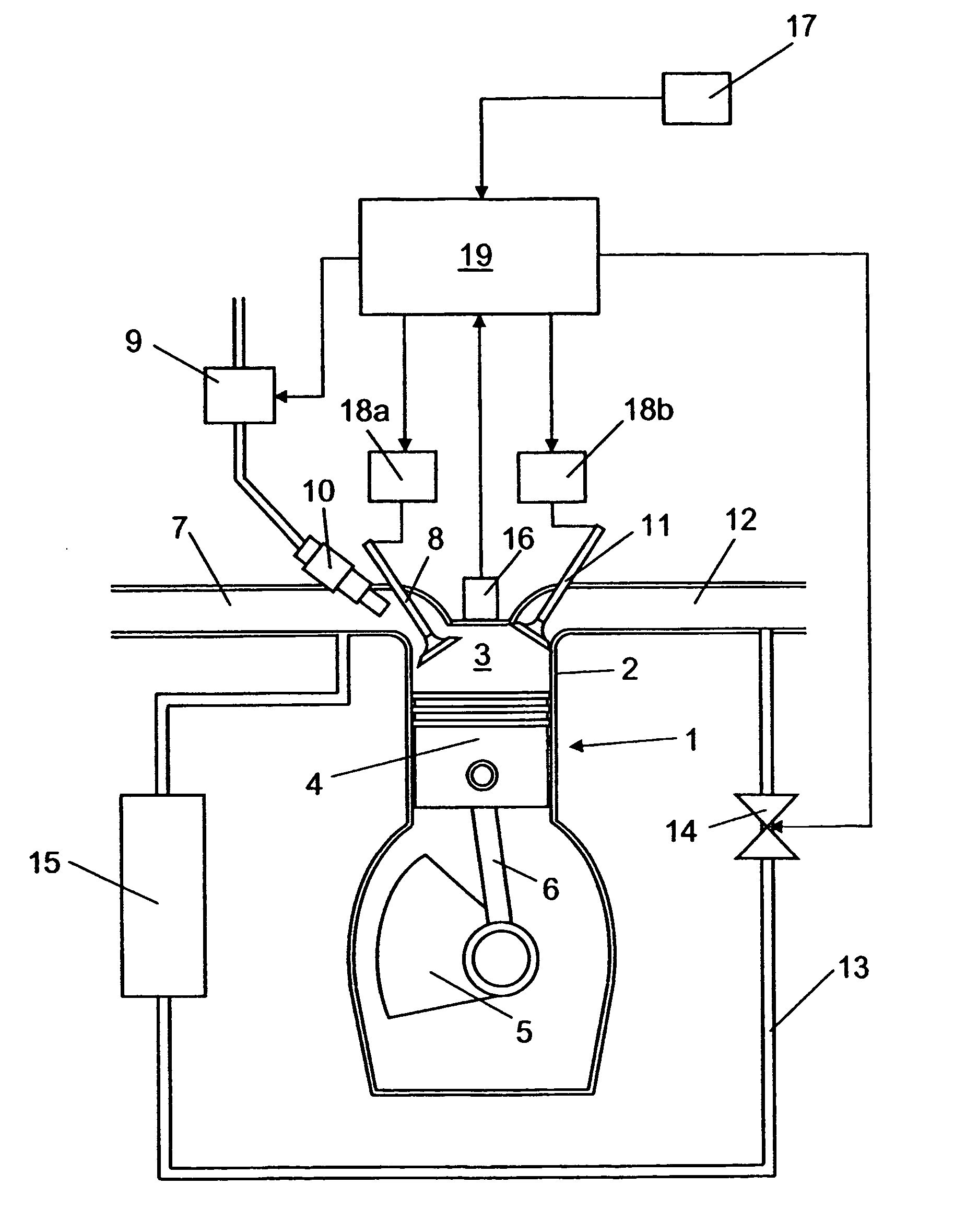
[0022]FIG. 1 depicts an arrangement for controlling a combustion engine 1 of the type in which a homogeneous mixture of fuel and air is compressed until self-ignition of the mixture takes place due to the heat arising during the compression. Such an engine 1 is usually called an HCCI (Homogeneous Charge Compression Ignition) engine. An HCCI engine may be regarded as a combination of an Otto engine and a diesel engine. A cylinder 2 of the engine 1 is depicted here. The engine 1 may of course have substantially any desired number of such cylinders 2. The engine 1 comprises a combustion chamber 3 which is bounded downwards in the cylinder 2 by a movable piston 4. The piston 4 is connected to a crankshaft 5 by a connecting rod 6. The movements of the piston 4 in the cylinder 2 are converted to rotary movement of the crankshaft 5.

[0023]When the piston 4 moves downwards in the cylinder 2 and an inlet valve 8 is open, air is drawn into the expanding combustion chamber 3 via an inlet line 7...


PUM


Abstract

An arrangement and a method for controlling a combustion engine, e.g. of the type called HCCI engine. A control unit for controlling the self-ignition of the fuel mixture towards an optimum crankshaft angel (cadiopt) within a load range (Ltot). The load range (Ltot) can be divided into at least two subranges (LI, LII) and the control unit is adapted to controlling the self-ignition of the fuel mixture towards an optimum crankshaft angle (cadiopt) within a first subrange (LI) by means of a strategy (I) which entails a variable amount of hot exhaust gases being supplied to or retained in the combustion chamber, and within a second subrange (LII) by means of another strategy (II) which entails the effective compression ratio (c) in the cylinder being varied.

Description

CROSS REFERENCE TO RELATED APPLICATION[0001]The present application is a 35 U.S.C. §§ 371 national phase conversion of PCT / SE2004 / 001211, filed 19 Aug. 2004, which claims priority of Swedish Application No. 0302246-4, filed 20 Aug. 2003. The PCT International Application was published in the English language.BACKGROUND TO THE INVENTION, AND STATE OF THE ART[0002]The present invention relates to an arrangement and a method for controlling a combustion engine so that self ignition occurs at an optimum crankshaft angle by control of the compression ratio in the cylinder.[0003]One type of such combustion engines are called HCCI (Homogeneous Charge Compression Ignition) engines and may be regarded as a combination of an Otto engine and a diesel engine. In HCCI engines, a homogeneous mixture of fuel and air is compressed in a combustion chamber until self-ignition of the fuel mixture takes place. Advantages of HCCI engines are that they produce low discharges of nitrogen oxides NOx and so...

Claims


Application Information

Patent Timeline
Patent Type & Authority Patents(United States)
IPC IPC(8): F02D13/02F02B1/12F02M25/07F02D41/30F02M51/06F02M69/04
CPCF02B1/12F02D13/0215F02D13/0269F02D35/023F02D35/028F02D41/0052F02D41/006F02D41/3035F02M69/044F02D13/0265F02D2041/001F02M51/06Y02T10/128Y02T10/142Y02T10/47Y02T10/12Y02T10/40
Inventor LINDERYD, JOHANAGRELL, FREDRIK
Owner SCANIA CV AB
Why Eureka
Try Eureka