Tarpaulin locking and tensioning mechanism

Inactive Publication Date: 2009-04-30
ROLL TITE
View PDF11 Cites 6 Cited by
  • Summary
  • Abstract
  • Description
  • Claims
  • Application Information

AI Technical Summary

Benefits of technology

[0007]Preferably, the rod is threaded for adjustment within the support. Also, preferably, the stop element further includes a vibration damping element, such as a disk spring, to suppress the vibrational forces from the tensioned tarp. Preferably the stop element is pivotable between a

Problems solved by technology

However, an issue arises in that the tarp must be capable of maintaining a certain degree of tension when covering the bed to prevent damage to the tarp or the cargo protected by the tarp during transport.
A difficulty with the Cramaro system is the need to rotate the crank in opposite directions to ensure that the lev

Method used


Image

  • Tarpaulin locking and tensioning mechanism
  • Tarpaulin locking and tensioning mechanism
  • Tarpaulin locking and tensioning mechanism

Examples


Embodiment Construction

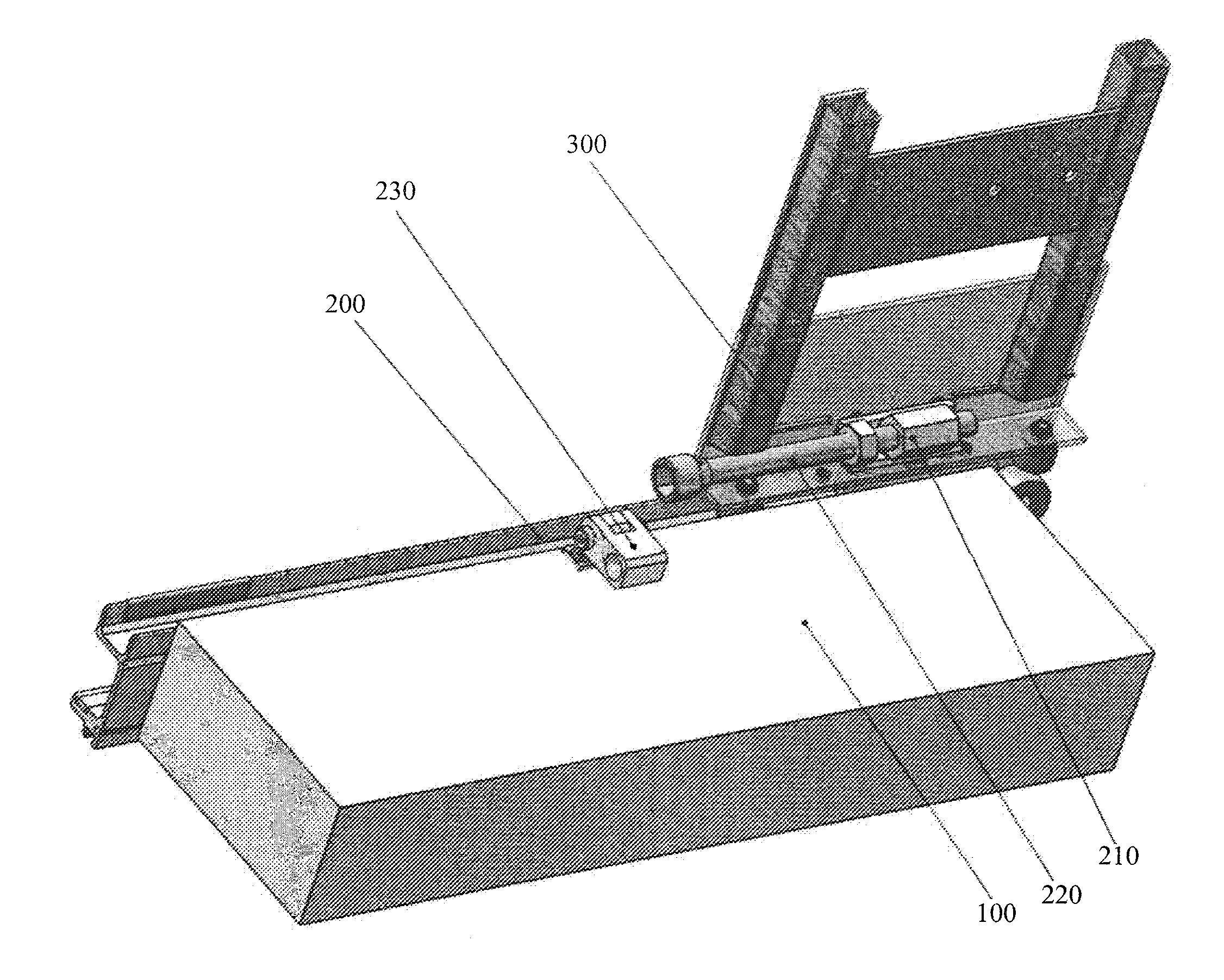
[0016]The invention presented herein comprises a locking and tensioning assembly for tensioning a tarpaulin (tarp) which is used to cover the cargo area of a vehicle, typically an open-bed or flat-bed truck.

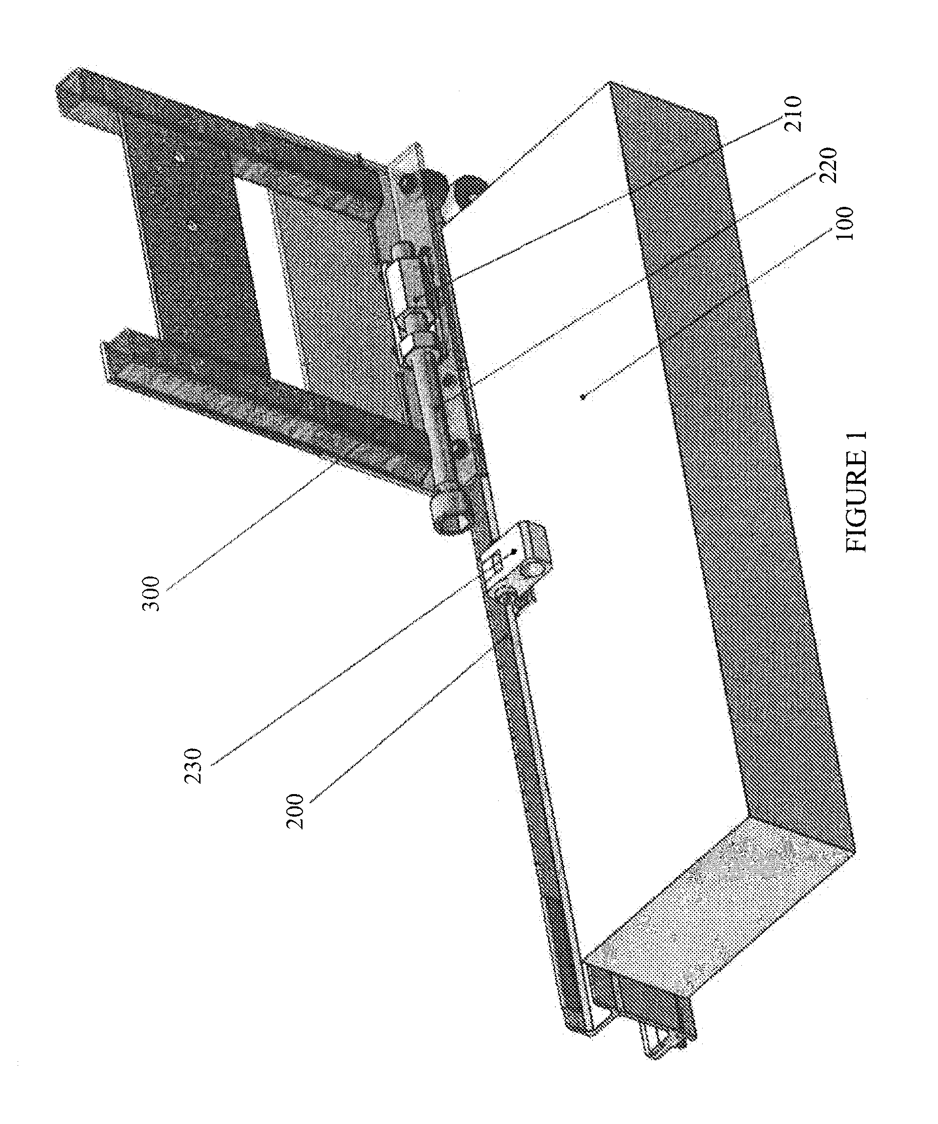
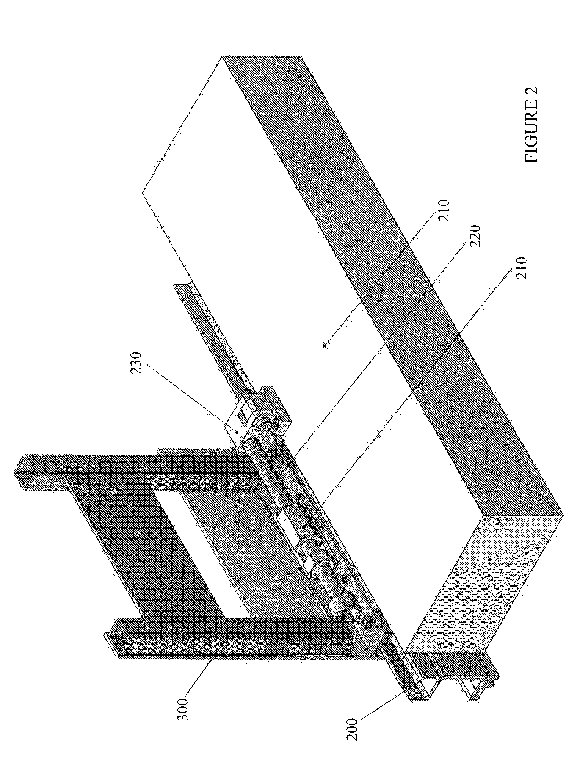
[0017]The tarp tensioning assembly is shown in an open (unlocked) position in perspective in FIG. 1 and a closed (locked) position in perspective in FIG. 2. Corresponding top views are shown in FIGS. 3 and 4. The rear bow 300 for mounting the tarpaulin is mounted on a track 200 coupled to the deck floor 100, allowing for movement along a horizontal axis relative to the deck for the purpose of tensioning the tarp (not shown). A universal support 210 is mounted to the bow 300 and supports a rod 220, which can be rotated via threads to adjust its position relative to the support 210.

[0018]A stop element 230 is pivotally mounted to the floor 100. The stop element 230 can be pivoted between a release position adjacent to the track 200, as shown in FIGS. 2 and 4, and a lock position ov...


PUM


Abstract

The invention comprises a tensioning assembly for a tarpaulin, comprising: a) a track for mounting a bow for supporting the tarpaulin, the track enabling longitudinal movement of the bow along the track; b) a universal support coupled to bow and operative to support a rod, the rod being oriented substantially parallel to the track; c) a stop element, the stop element moveable from a position over the track to a position removed from said track, and said stop element operative to engage the rod when positioned over the track; and d) a tensioning adjustment mechanism, as part of one of the universal support, the rod and the stop element, the tensioning adjustment mechanism operative to adjust the position of the rod relative to the universal support and thereby maintain the tarpaulin under tension when the rod is engaged to the stop element, wherein said tensioning assembly is operative to maintain the bow substantially parallel to the track while under tension.

Description


Claims


Application Information

Patent Timeline
Owner ROLL TITE
Why Eureka
Try Eureka