
Omnidirectional electric fan and fan blade structure

a technology of electric fans and blades, applied in the direction of liquid fuel engines, marine propulsion, vessels, etc., can solve the problems of increasing cost and space, increasing technology, and generating unidirectional airflow,

Inactive Publication Date: 2009-04-30
TSEN SAMSON
View PDF5 Cites 7 Cited by
  • Summary
  • Abstract
  • Description
  • Claims
  • Application Information

AI Technical Summary

Benefits of technology

[0003]The primary objective of the present invention s to provide an fan blade structure, which can generate a 360-degree air flow and outperform the conventional technology that is hard to provide airflows by 360 degrees at the same time.

Problems solved by technology

All the abovementioned fan blades are hard to provide wide-range airflow but can only generate unidirectional airflow.
However, such a solution increases cost and wastes space.
However, such a technology also increases considerable cost and has an overweight problem.
Besides, airflow is not really multidirectional at the same time.
From the above discussion, it is known that most of the conventional electric fans generate only unidirectional airflow.

Method used


Image

  • Omnidirectional electric fan and fan blade structure
  • Omnidirectional electric fan and fan blade structure
  • Omnidirectional electric fan and fan blade structure

Examples


Embodiment Construction

[0012]The technical contents of the present invention will be described in detail in cooperation with the drawings below.

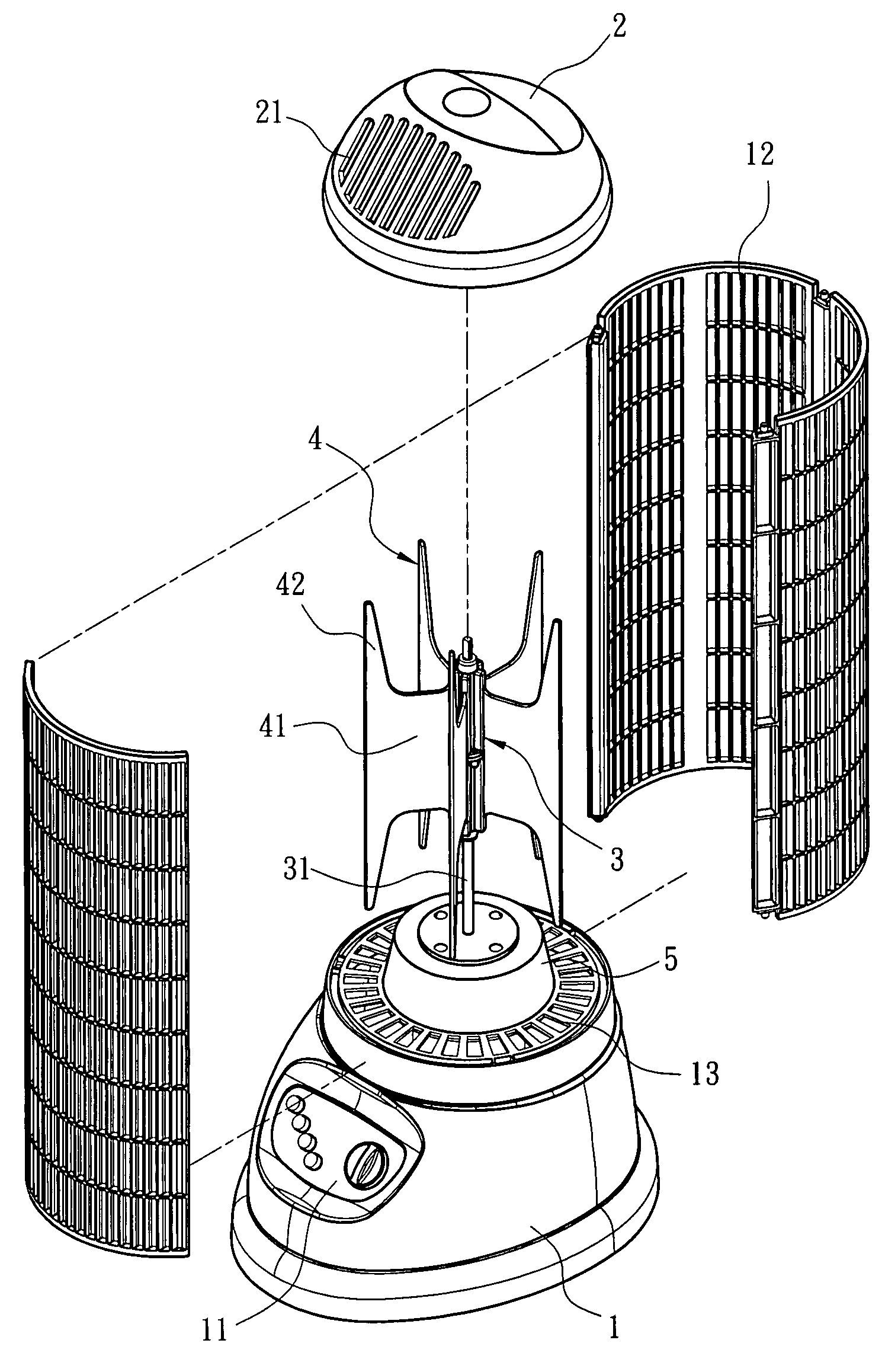
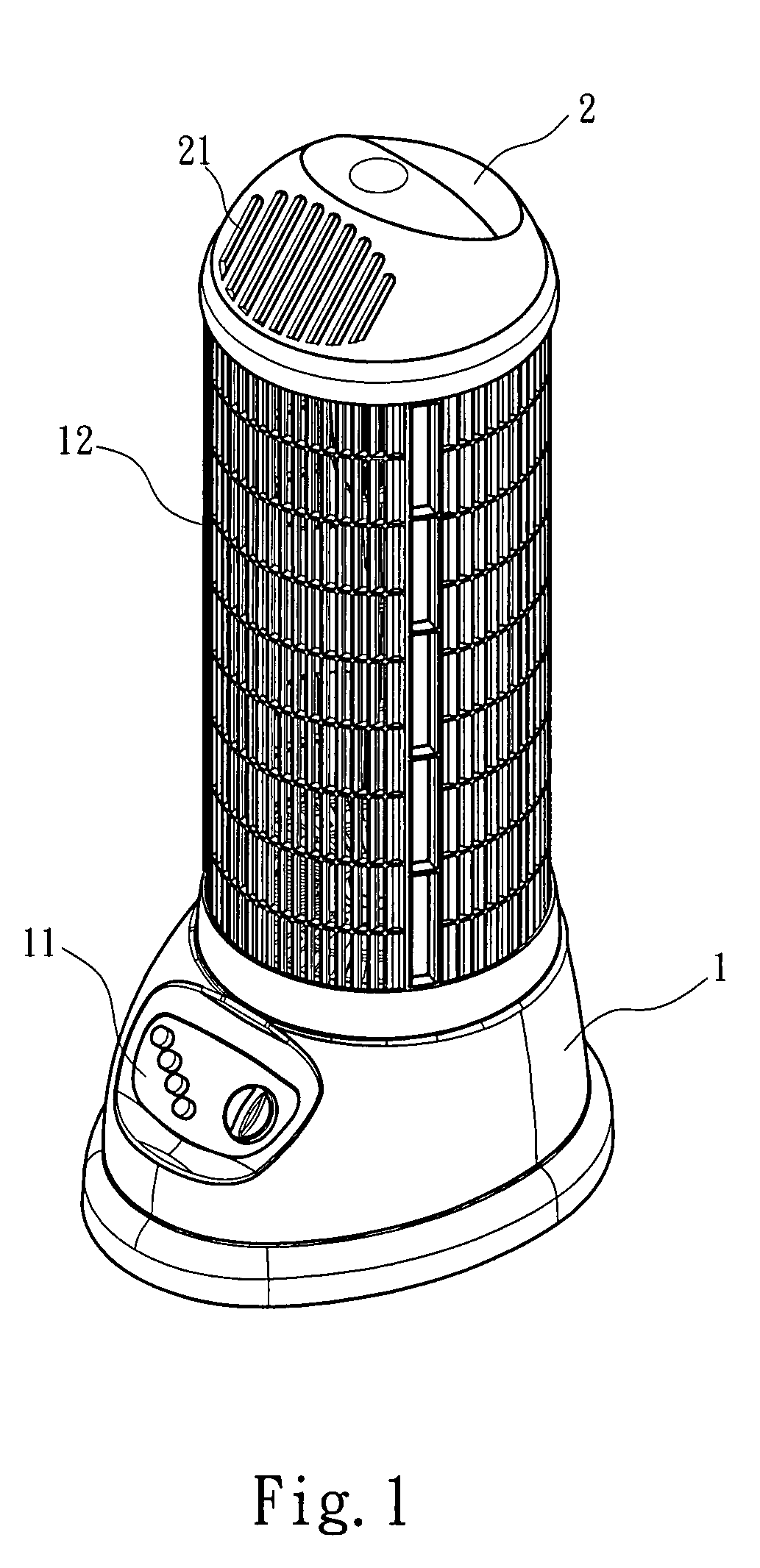
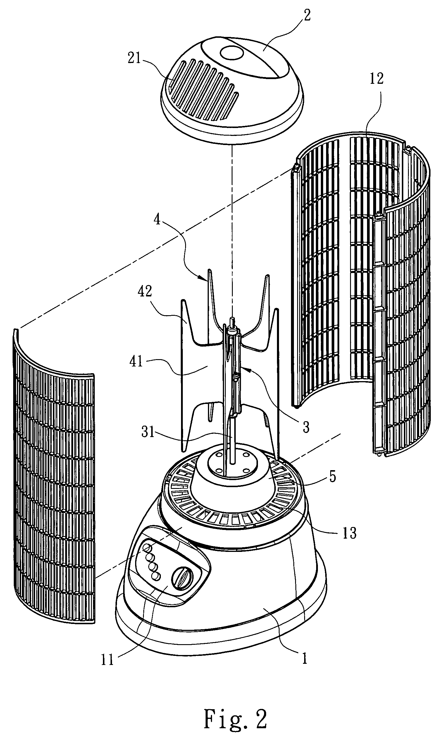
[0013]The fan blade structure of the present invention is installed in an omnidirectional electric fan and powered by the omnidirectional electric fan to rotate and form pressure drop to generate airflow. Refer to FIG. 1 and FIG. 2 respectively a perspective view and an exploded view schematically showing one embodiment of the present invention. The omnidirectional electric fan of the present invention comprises: a seat 1, a plurality of fan grills 12, a dynamic source 5, a cover 2 and a fan blade structure having a central pole 3 and a plurality of fan blades 4. The central pole 3 is coupled to the dynamic source 5 through a transmission shaft 31. The dynamic source 5 is fixedly installed in an accommodation room of the seat 1. The surface of the seat 1 has a control panel 11 used to control the operation of the dynamic source 5. The seat 1 has a plurality of low...


PUM


Abstract

The present invention discloses an omnidirectional electric fan and a fan blade structure. The fan blade structure comprises: a transmission shaft, a lower connection element, an upper connection element and a plurality of fan blades. The fan blades are radiately secured in between said lower connection element and said upper connection element. Each fan blade has a root portion and a wing portion. The wing portion extends from the edge of the root portion toward both sides to form a wider portion at the border of the fan blade. The fan blade structure cooperates with a seat, a cover, a plurality of fan grills and a dynamic source to from an omnidirectional electric fan.

Description

FIELD OF THE INVENTION[0001]The present invention relates to an omnidirectional electric fan and a fan blade structure, wherein the active areas of the fan blade are designed to create a first pressure zone and a second pressure zone, and whereby the fan blade structure can realize an omnidirectional electric fan.BACKGROUND OF THE INVENTION[0002]Rotating fan blades to generate airflow is a long-standing technology, which is mostly used in cooling or air circulation. A Taiwan patent No.M302003 disclosed a “Structure of Fan Blade Assembly for Exhaust / Suction Blower”, wherein the tilt angle of fan blades is adjusted to vary the intensity of airflow. A Taiwan patent No.M300731 disclosed a “Fan Blade Structure for External Rotor Motor”, wherein counter weights are added to fan blades. A Taiwan patent No.M300427 disclosed a “Multi-Layer Fan Blade Structure”, wherein several sets of fan blades are arranged on a hub, and a fixed ring is interposed in between each two sets of fan blades. All...

Claims


Application Information

Patent Timeline
Patent Type & Authority Applications(United States)
IPC IPC(8): F04D19/00F03B3/12
CPCF04D17/04F04D29/30F04D29/282F04D29/263
Inventor WU, MIN-I
Owner TSEN SAMSON
Learn More