Temperature control device and method for generating a temperature-controlled air flow

a technology of temperature control device and temperature control system, which is applied in the direction of temperatue control, process and machine control, instruments, etc., can solve the problems of reducing the efficiency of the climate control device or the climate control system, increasing power consumption, and increasing the risk of mucous membrane drying

Inactive Publication Date: 2013-04-25
BEHR GMBH & CO KG
View PDF12 Cites 14 Cited by
  • Summary
  • Abstract
  • Description
  • Claims
  • Application Information

AI Technical Summary

Benefits of technology

[0009]It is therefore an object of the present invention to provide an improved temperature control device for a vehicle, an impro...

Problems solved by technology

This causes an increase in power consumption, as a result of which the (energy) efficiency of the climate control device or cli...

Method used


Image

  • Temperature control device and method for generating a temperature-controlled air flow
  • Temperature control device and method for generating a temperature-controlled air flow
  • Temperature control device and method for generating a temperature-controlled air flow

Examples


Embodiment Construction

[0031]In the following description of the preferred exemplary embodiments of the present invention, the same or similar reference characters are used for the elements with a similar action and shown in the different drawings, whereby a repeated description of these elements is omitted.

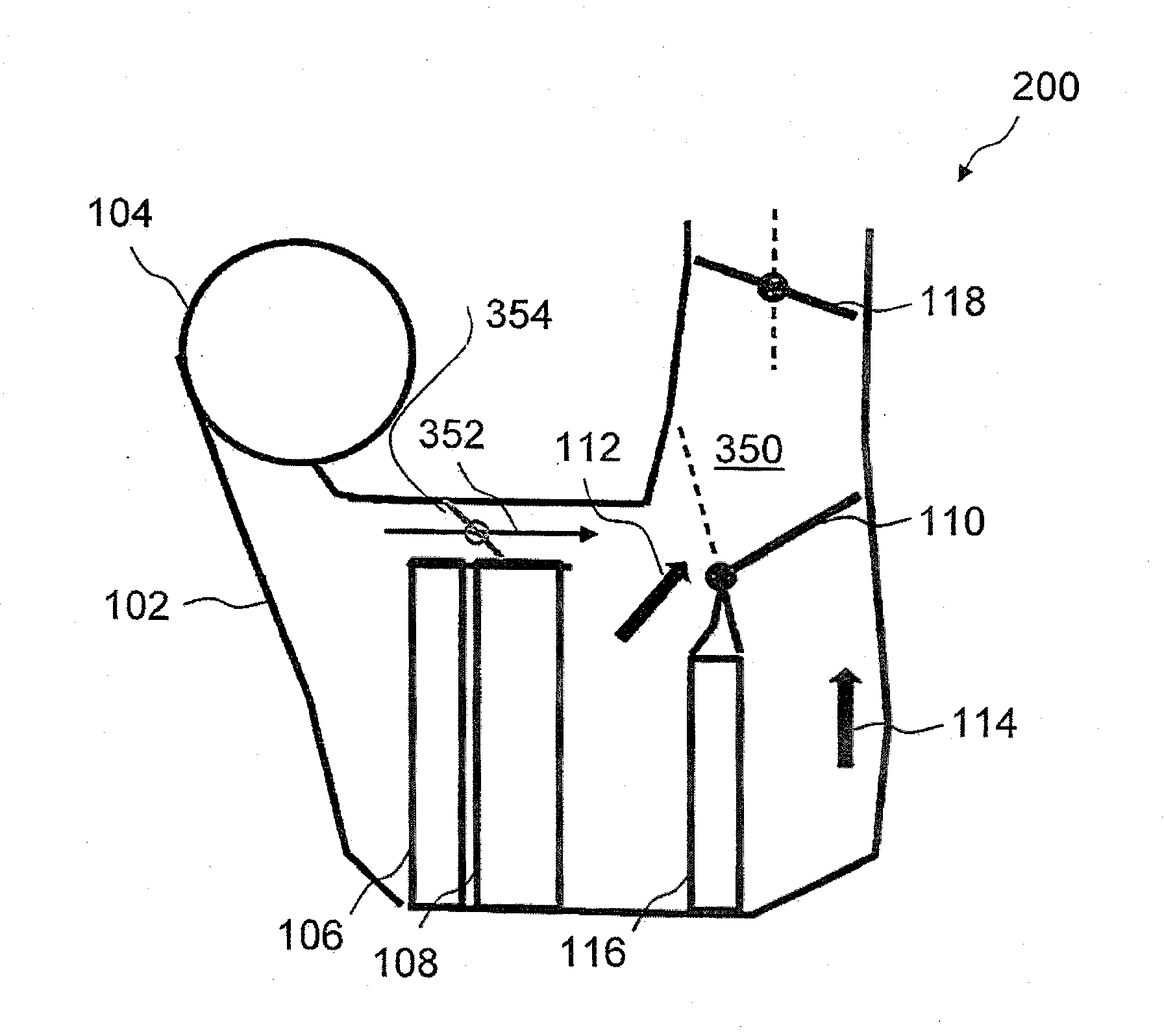
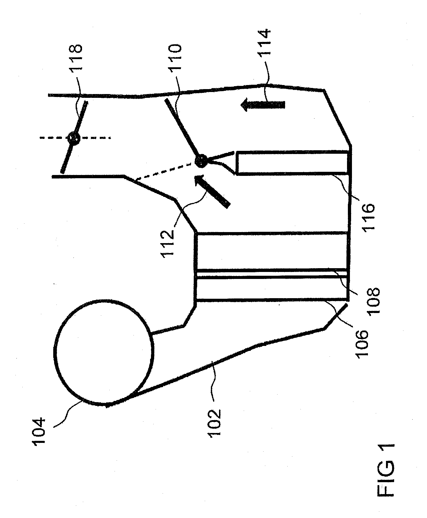
[0032]FIG. 1 shows a schematic illustration of a climate control device with air-side regulation. The climate control device has a housing 102 into which an air flow is blown in by a blower 104. The air flow is guided through a filter 106 and an evaporator 108. Next, the air flow branches and, depending on the position of a mixing valve 110, follows either a cold path 112 or a heat path 114, which passes over a heater 116, to one or more outlets of housing 102. The outlet / outlets is / are released or blocked by shut-off valve(s) 118.

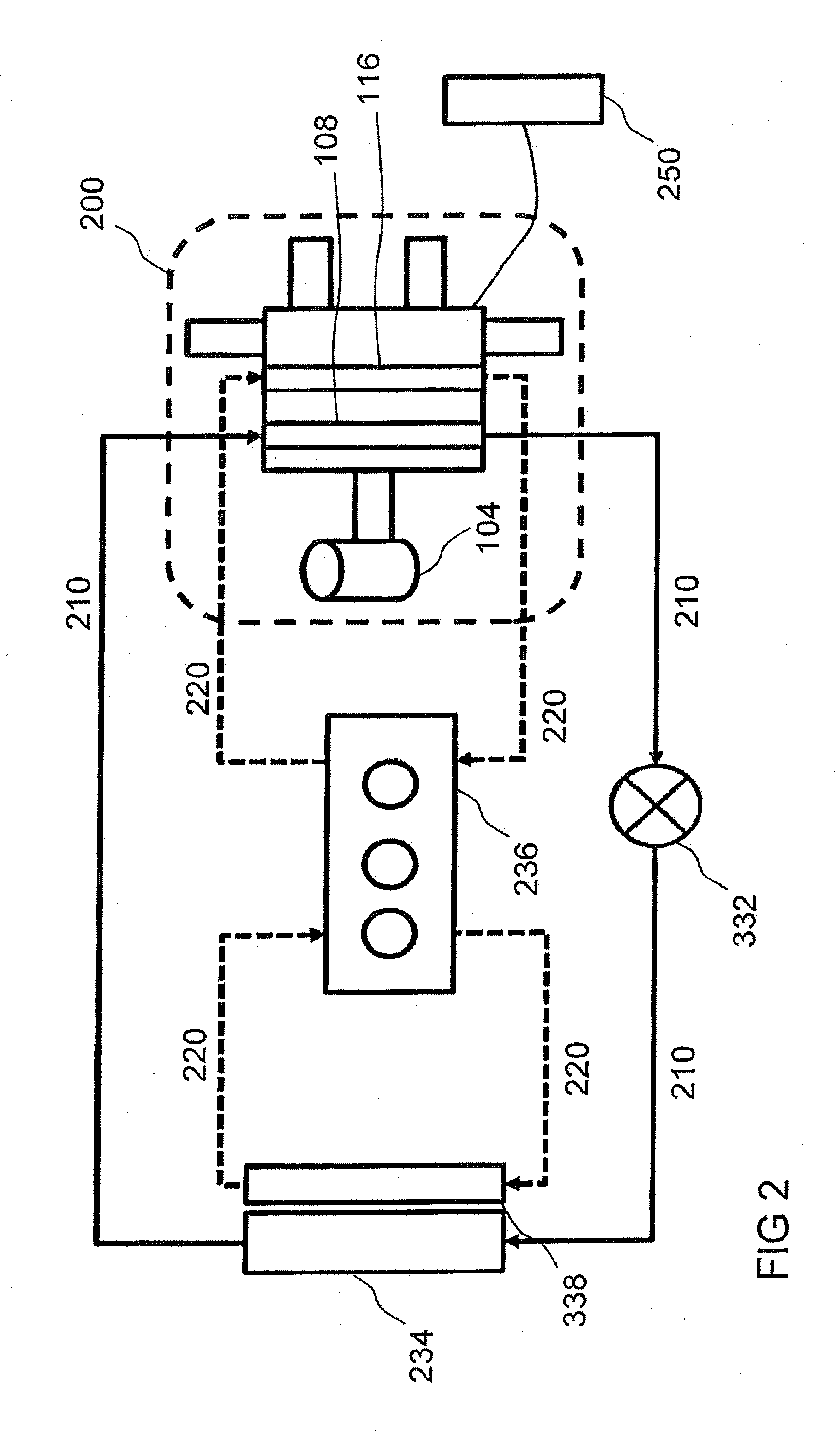
[0033]FIG. 2 shows a climate control system with a temperature control device or a climate control device 200 according to an exemplary embodiment of the present invention. T...


PUM


Abstract

A temperature control device for a vehicle is provided that includes a first air duct for guiding a first portion of an air flow and a second air duct for guiding a second portion of an air flow. A cooling device is disposed in the first air duct, in order to cool the first portion of the air flow. A mixer device is provided for mixing the first air flow from the first air duct with the second portion of the air flow from the second air duct in order to generate a temperature controlled air flow.

Description

[0001]This nonprovisional application is a continuation of International Application No. PCT / EP2011 / 058189, which was filed on May 19, 2011, and which claims priority to German Patent Application No. DE 10 2010 029 495.0, which was filed in Germany on May 31, 2010, and which are both herein incorporated by reference.BACKGROUND OF THE INVENTION[0002]1. Field of the Invention[0003]The present invention relates to a temperature control device for a vehicle, to a control unit for a temperature control device, and to a method for generating a temperature-controlled air flow for a vehicle.[0004]2. Description of the Background Art[0005]In a cooling mode, setpoint ventilation air temperatures above about 10° C. can no longer be generated in all cases with conventional climate control devices or climate control systems directly at an evaporator. The reason for this can be, for example, that the rotational speed at the compressor would have to fall below the minimal allowable speed or that t...

Claims


Application Information

Patent Timeline
IPC IPC(8): B60H1/00G05D23/13
CPCB60H1/0005G05D23/138B60H2001/00164A45F3/04A45F3/06A45F3/10A45F2003/025A45F2003/166
Inventor SCHALL, MATTHIAS
Owner BEHR GMBH & CO KG
Why Eureka
Try Eureka