Susceptor for hybrid microwave sintering system, hybrid microwave sintering system including same and method for sintering ceramic members using the hybrid microwave sintering system

Inactive Publication Date: 2006-01-26
DEL REGNO GARY E
View PDF3 Cites 22 Cited by
  • Summary
  • Abstract
  • Description
  • Claims
  • Application Information

AI Technical Summary

Benefits of technology

[0014] It is an object of the present invention to overcome the drawbacks described above. It is also an object of the present invention to provide a hybrid microwave sintering system that can effectively sinter a large material load using an economic, commercially available microwave furnace with a standard 2.45 GHz frequency magnetron source. In conjunction therewith, it is an object of the present inv

Problems solved by technology

These decreased processing times and energy savings associated with microwave sintering, however, can only be applied to materials that can be readily processed by microwaves.
Susceptibility in some materials diminishes, however, at a certain temperature where the dielectric loss of the material becomes sufficiently high enough such that the same material becomes reflective to microwave energy, even at an elevated temperature.
Many ceramic materials, however, such as SiO2, Al2O3 and ZrO2, have a low room temperature dielectric loss factor and are virtually transparent to microwaves at room temperature, that is, these materials do not substantially reflect or absorb microwaves.
Indeed, sintering ceramic materials using direct microwave systems has been problematic if not impossible since most ceramic materials are not readily susceptible to microwaves emitted at a frequency of 2.45 GHz, which is a commercially desirable microwave frequency for materials processing.
Large-scale use of any frequency outside of the specific use allocation range detrimentally interferes with the intended applications allocated to the specific frequency range.
As such, viable microwave processes for those applications are limited to the frequencies allocated by the FCC.
Generally speaking, however, higher operating frequencies require a more expensive operating system.
As the power requirements

Method used


Image

  • Susceptor for hybrid microwave sintering system, hybrid microwave sintering system including same and method for sintering ceramic members using the hybrid microwave sintering system
  • Susceptor for hybrid microwave sintering system, hybrid microwave sintering system including same and method for sintering ceramic members using the hybrid microwave sintering system
  • Susceptor for hybrid microwave sintering system, hybrid microwave sintering system including same and method for sintering ceramic members using the hybrid microwave sintering system

Examples


Example

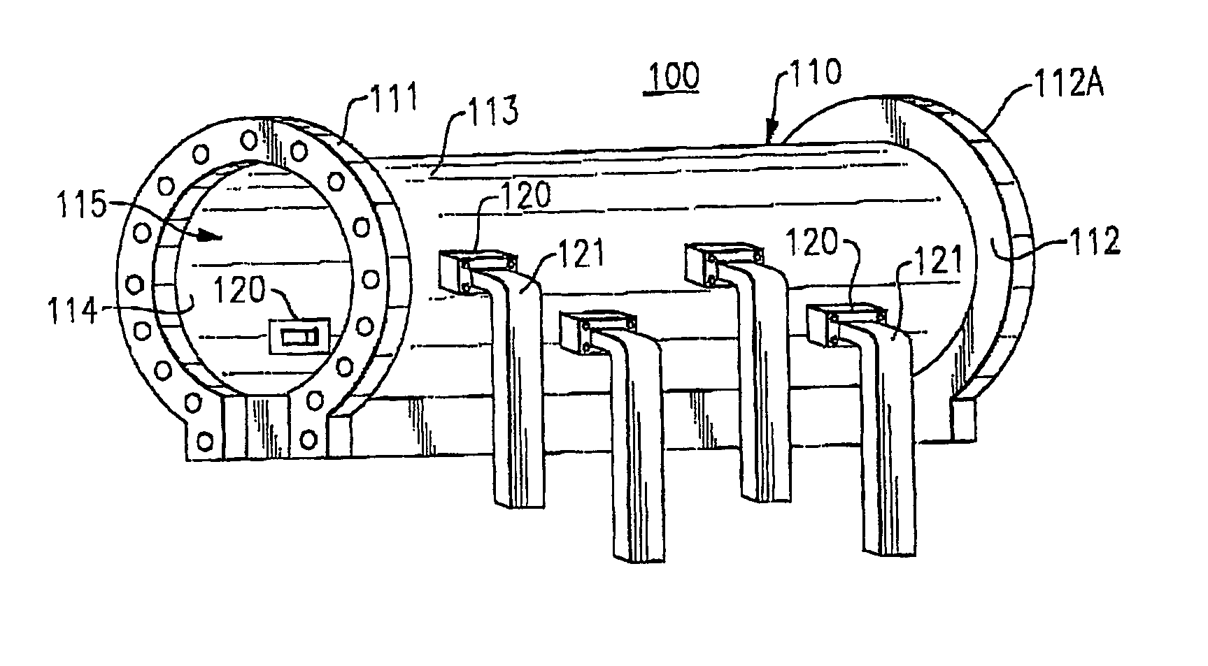
[0042]FIG. 1 is a perspective end view of an applicator 110 for a microwave hybrid heating system 100 according to one embodiment of the present invention. The applicator 110 is preferably made from a material that is reflective to microwaves and has a substantially cylindrical configuration with a flattened portion for stability and support. The applicator 110 extends in a longitudinal direction from a first end 111 to an opposed second end 112 and has an outer surface 113 and an inner surface 114 to define an elongate microwave chamber 115. The flattened portion provides a stable setting surface for loads (materials) that are processed within the microwave chamber 115 of the applicator 110, and also allows for the conveyance of materials by a belt or other appropriate transport means along the longitudinal distance between the first end 111 and the second end 112. The first end of the microwave chamber 115 is further defined by the inner surface 111A of a first flanged end cover 1...


PUM


Abstract

A susceptor for a microwave hybrid heating system is provided, including a hollow member comprising a heat resistant material that does not substantially absorb or reflect microwave energy at room temperature and a substance contained within the hollow member. The substance substantially immediately couples to microwave energy at room temperature to form a plasma that emits radiant energy substantially immediately. A microwave hybrid heating system and a continuous microwave hybrid heating system including at least one susceptor according to the present invention are provided, as well as a method for sintering ceramic members using a microwave hybrid heating system according to the present invention.

Description

CROSS REFERENCE TO RELATED APPLICATION [0001] This application claims the benefit of U.S. Provisional Application Ser. Nos. 60 / 514,871 filed Oct. 27, 2003 and 60 / 531,742 filed Dec. 22, 2003, the entireties of which are incorporated herein by reference.FIELD OF THE INVENTION [0002] The present invention relates to a susceptor for a microwave hybrid heating system, a microwave hybrid heating system including such a susceptor, and a method for sintering ceramic materials in such a hybrid microwave heating system. BACKGROUND OF THE INVENTION [0003] Microwave energy offers a fast and effective sintering process that can reduce processing time by over 50% and which offers energy savings as a result. These decreased processing times and energy savings associated with microwave sintering, however, can only be applied to materials that can be readily processed by microwaves. The applicability of direct microwave sintering to specific materials is based on the characteristics of the material,...

Claims


Application Information

Patent Timeline
IPC IPC(8): H05B6/64
CPCH05B6/80
Inventor DEL REGNO, GARY E.
Owner DEL REGNO GARY E
Why Eureka
Try Eureka