Toasting appliance

A technology of equipment and components, applied in the field of baking equipment with slender radiation elements, to achieve the effect of flexible energy and high energy efficiency

Inactive Publication Date: 2013-11-27
HANG SHUN HING
View PDF7 Cites 1 Cited by
  • Summary
  • Abstract
  • Description
  • Claims
  • Application Information

AI Technical Summary

Problems solved by technology

While such roasters thus provide advantages, there remains a need for improvements

Method used


Image

  • Toasting appliance
  • Toasting appliance
  • Toasting appliance

Examples


Embodiment Construction

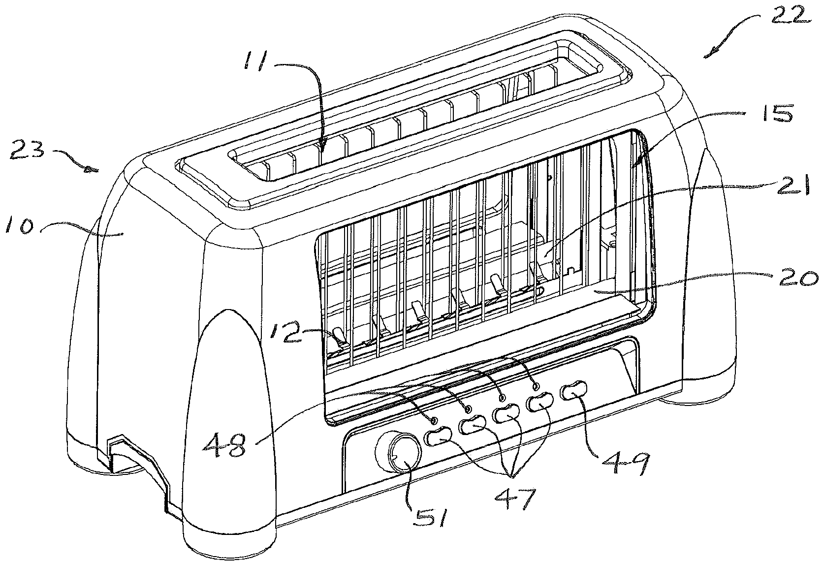
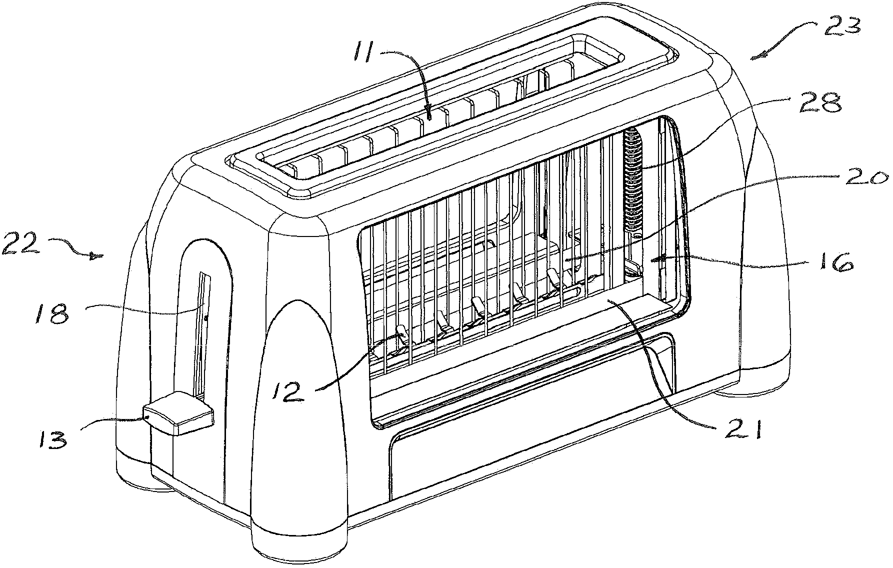
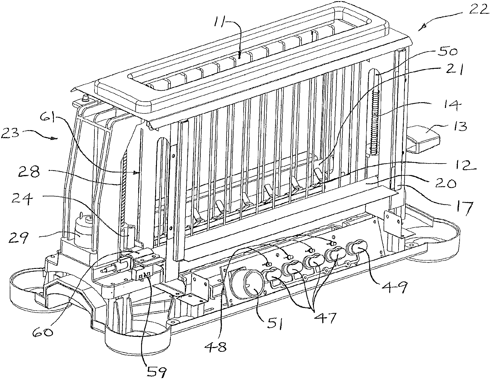
[0030] refer to figure 1 and 2, the roaster according to the present invention comprises: a casing 10, at the top of which is a slot 11 for receiving food such as a piece of panel. The slot 11 extends substantially between longitudinally opposite first and second end portions 22, 23 of the toaster. The food is supported on carriages 12 visible through windows 15 , 16 arranged in opposite sides of the housing 10 . The roaster is of the pop-up type, with the carriage 12 mounted at the first end 22 on an upright guide 50, allowing food to be lowered for toasting and automatically raised when toasting is complete. Carriage 12 may be cantilevered, being supported only on upright guides 50 and extending horizontally to cantilever food. A spring 14 is connected at one end to the carriage 12 and at the other end to a chassis 17 in order to push the carriage 12 upwards. A handle 13 protruding from an upstanding slot in the housing is provided for lowering the carriage 12 . The toa...


PUM


Abstract

A toasting appliance includes a pair of elongate radiant elements, and provides relative movement between the radiant elements and the foodstuff to be toasted, so as to traverse the foodstuff with the elements, or vice versa. For faster operating speed and improved efficiency, a control circuit receives a toasting-control signal and controls a switch to energise the elements only during a portion of the amplitude of relative displacement produced between the carriage and elements, the portion being defined by the toasting-control signal. Correct movement of the elements is monitored by a control circuit that de-energises the elements when, due to a fault, one of the elements and the carriage departs from a defined velocity profile.

Description

technical field [0001] The present invention relates generally to toasting apparatus, and more particularly to toasting apparatus having an elongated radiating element and which provides relative motion between the radiating element and the food to be grilled so that the element across the food, or vice versa. Background technique [0002] US Patent No. 6668706 describes a roaster of the above type in which a pair of elongated radiating elements are arranged upright and scanned back and forth across the food to roast both sides simultaneously. This arrangement provides high speed operation compared to conventional toasters comprising planar elements. A window is provided in the body of the roaster for viewing the moving elements and items being roasted. Due to the regular motion required to complete each toasting cycle, a visual indication of the remaining toasting time is provided to the user. While such roasters thus provide advantages, there remains a need for improvem...

Claims


Application Information

Patent Timeline
IPC IPC(8): A47J37/06A47J37/04A23L5/30
CPCA23L1/0128A23L1/025A47J37/08A47J37/0857A23L5/15
Inventor 张文辉
Owner HANG SHUN HING
Why Eureka
Try Eureka