Starting device for discharge lamps

Inactive Publication Date: 2016-11-24
EASYLUMEN
View PDF2 Cites 0 Cited by
  • Summary
  • Abstract
  • Description
  • Claims
  • Application Information

AI Technical Summary

Benefits of technology

[0014]The main advantage of this invention is basically the fact that the overall energy efficiency of the luminaire reaches a high value, therefore with low energy costs for operation.
[0015]Another advantage is due to the fact that the ballast does not suffer from reduced efficiency and technical performance during operation outdoors and in a hot environment, nor is it affected by the voltage oscilla

Problems solved by technology

Such limits basically consist of some noisiness during operation caused by lamellar pack vibrations, the poor tolerance of voltage oscillations on the electric networks at various times of day, accentuated thermal dispersion, with consequent reduction of component lifetime, and above all low overall energy efficiency obtainable with such ballasts.
In general, the above-mentioned various types of electronic devices for poweri

Method used


Image

  • Starting device for discharge lamps
  • Starting device for discharge lamps
  • Starting device for discharge lamps

Examples


Example

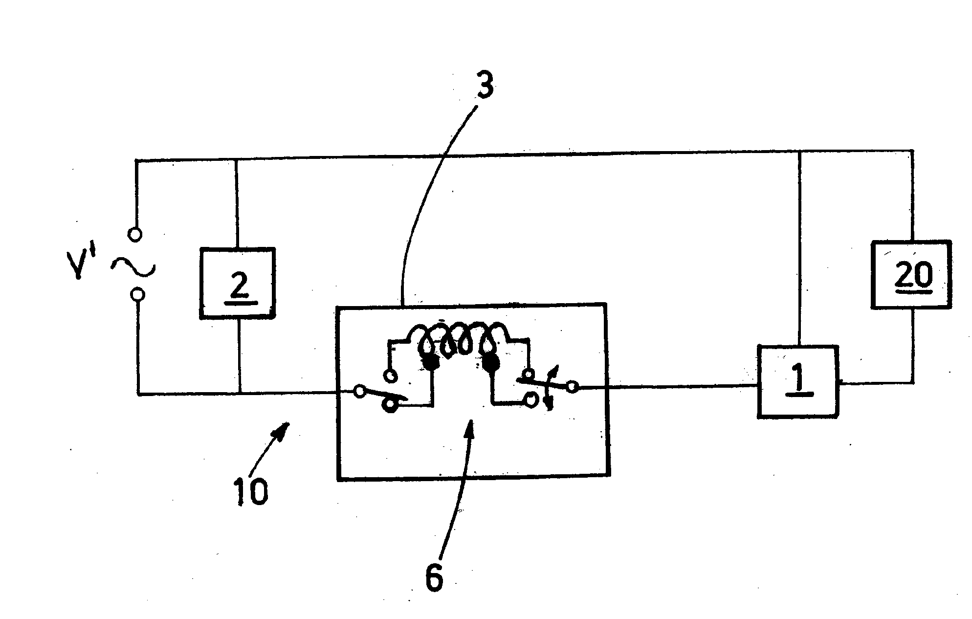
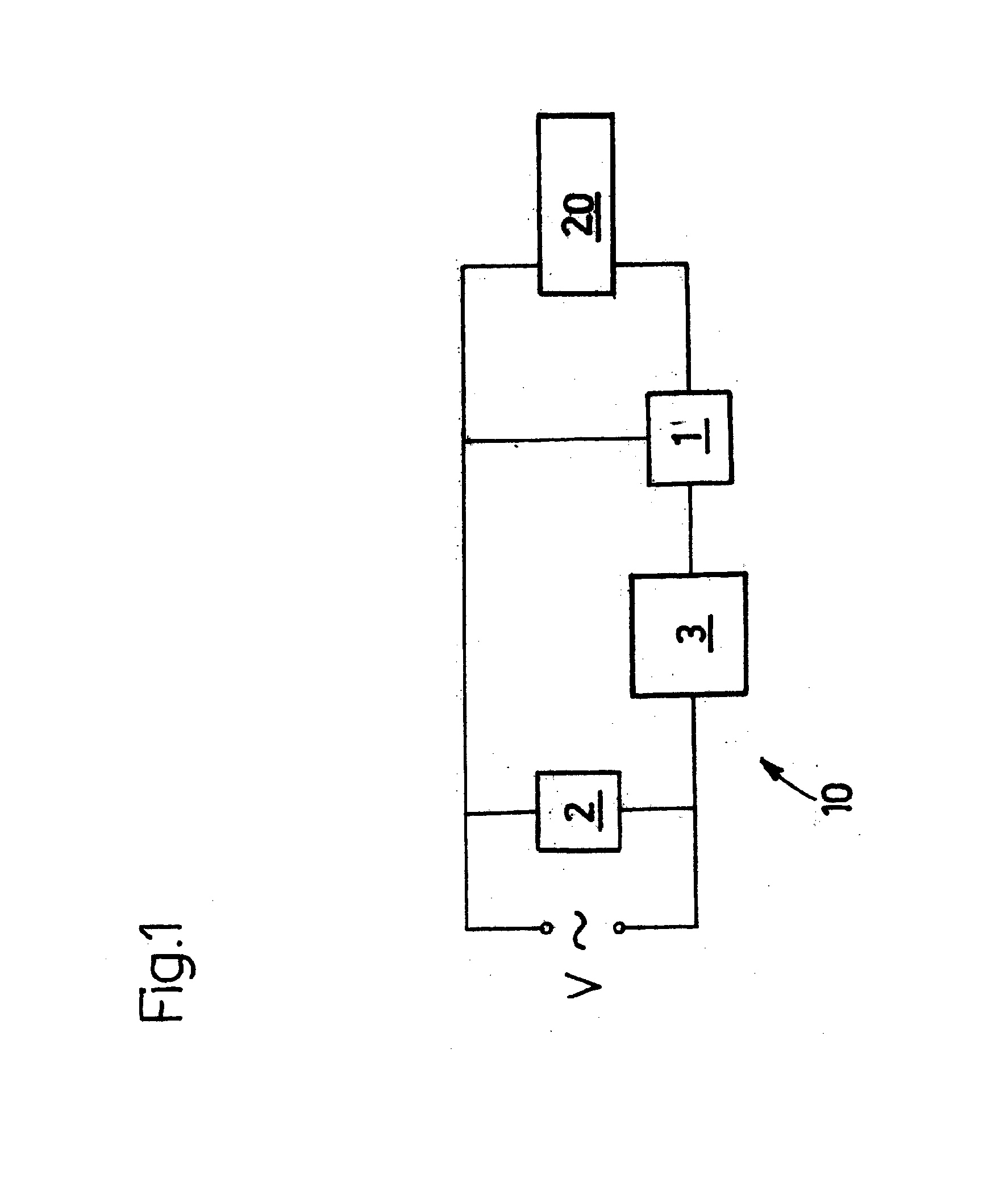
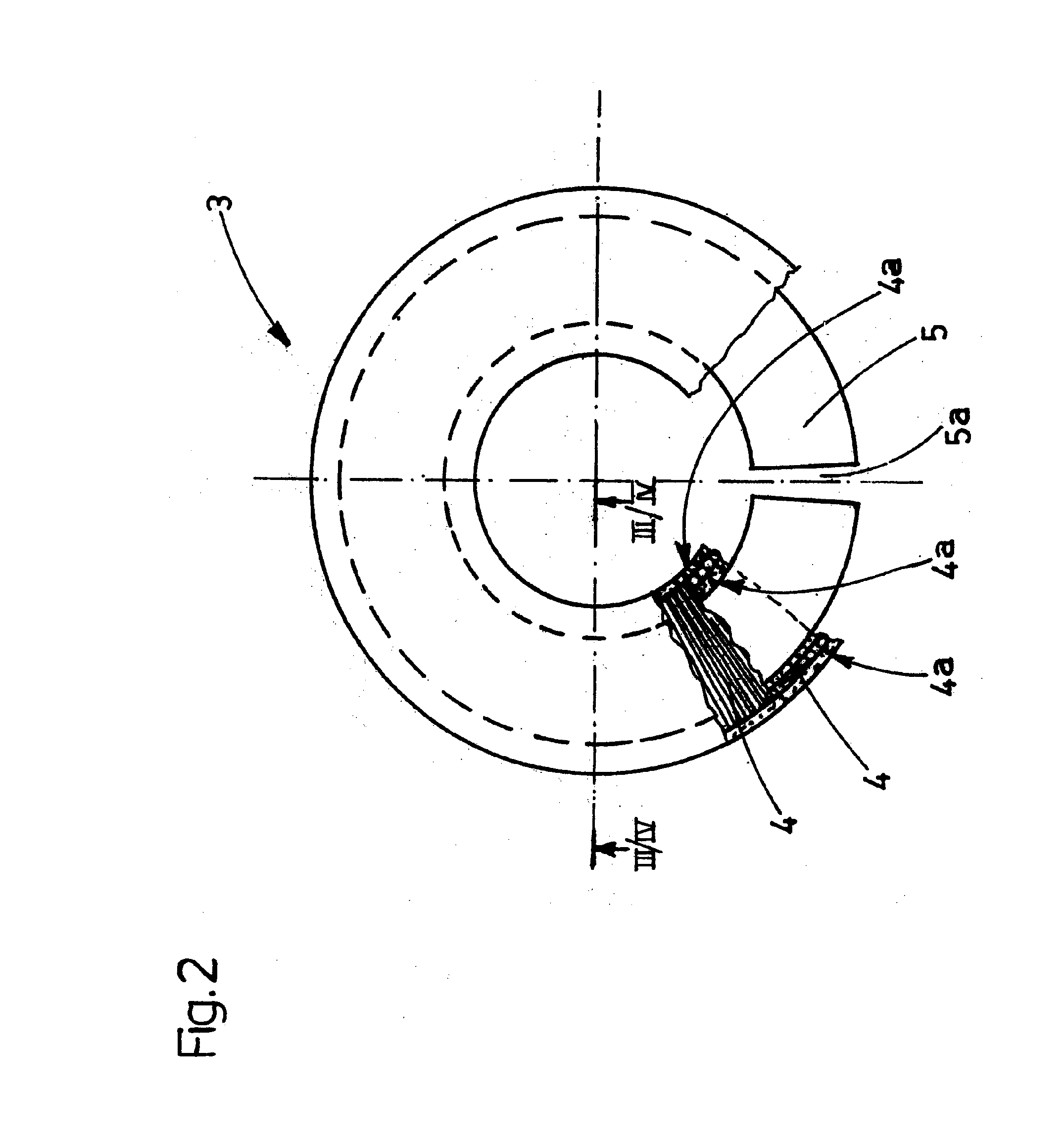
[0022]A starting device for discharge lamps comprises at least an ignitor 1 and a ferromagnetic ballast 3. The ferromagnetic ballast 3 is composed of at least a toroidal core 5, equipped with at least an air gap 5a, and an electric coil 4, wound around the toroidal core 5. That shape of the ferromagnetic ballast 3 allows the obtainment of lasting high energy efficiency, resulting in corresponding improved efficiency of the device 10 and the lamp 20 with which it is associated.

[0023]In a preferred embodiment of the invention, schematically illustrated in FIG. 1, the starting device 10 comprises a power factor correction capacitor 2 for the current drawn by the lamp 20 and by the ferromagnetic ballast 5.

[0024]The toroidal core 5 may be made in various ways: it may be composed of one or more small plates made of ferromagnetic material wound over themselves in a spiral, as shown in FIG. 4, of small plates of ferromagnetic material in a pack, as shown in FIGS. 2 and 3, or even solid ferr...


PUM


Abstract

A starting device for discharge lamps including an ignitor and a ferromagnetic ballast, composed of a toroidal core, equipped with at least an air gap, and an electric coil wound around the toroidal core.

Description

TECHNICAL FIELD[0001]This invention relates to a starting device for discharge lamps.[0002]In starting devices for discharge lamps, according to known technical criteria which have been widespread for some time now, at least a “starter” ignitor and a ballast must be present which, acting together, cause an overvoltage in the electrodes, contained in the lamp tube together with a gas. That overvoltage triggers an electric discharge which ionises the gas present in the tube, producing the emission of light radiation.[0003]After starting, the lamp switches to normal operation, in which the ballast takes on the function of stabiliser for the electric current drawn, so that the light radiation emitted is uniform and stable.BACKGROUND ART[0004]Said schematic operation can basically be traced back to traditional luminaires, which use a ballast composed of a core of small ferromagnetic plates in a pack, on which a metal conductor coil is wound, powered by alternating current mainly supplied...

Claims


Application Information

Patent Timeline
IPC IPC(8): H05B41/10H01F27/245H05B41/18
CPCH05B41/10H01F27/245H05B41/18H01F3/14H01F27/2895H01F30/16H01F38/10H01F38/12H01J7/34
Inventor MENGHI, ALBERTOFUOCHI, DEMOS
Owner EASYLUMEN
Why Eureka
Try Eureka