Rotary positive displacement flowmeter

Active Publication Date: 2011-07-14
ADVANCED FLOW SOLUTIONS INC
View PDF3 Cites 2 Cited by
  • Summary
  • Abstract
  • Description
  • Claims
  • Application Information

AI Technical Summary

Benefits of technology

[0045]The straight-line arrangement of the rotors more efficiently directs the flow path around the blocking rotor, not toward it. Much lower energy cost, lower pressure drop, and less vibration is generated by this invention because the straight line rotor axes configuration does not direct flow toward the blocking rotor at the inlet, nor at the outlet, nor between the displacement chambers. This more efficient flow path with fewer obstructions and fewer sharp turns may allow smaller devices to be constructed with the same flow capacity of larger prior art devices. That combined with its simplicity of design suggest this invention may offer significant cost advantages over comparable devices in a wide range of installations.
[0046]The invention resides in displacement rotors with a more prominent hub compared to any available in the art, with a radius large enough to route the flow completely around the blocking rotor, reducing its interference with the flow. Displacement rotor hubs performing this function are not found in prior art. The

Problems solved by technology

The cross-over feature also permits a smoother flow into the flowmeter chamber compared to currently existing designs where th

Method used


Image

  • Rotary positive displacement flowmeter
  • Rotary positive displacement flowmeter
  • Rotary positive displacement flowmeter

Examples


Example

[0066]As required, detailed embodiments of the present inventions are disclosed herein; however, it is to be understood that the disclosed embodiments are merely exemplary of the invention, which may be embodied in various forms. Therefore, specific structural and functional details disclosed herein are not to be interpreted as limiting, but merely as a basis for the claims and as a representative basis for teaching one skilled in the art to variously employ the present invention in virtually any appropriately detailed structure.

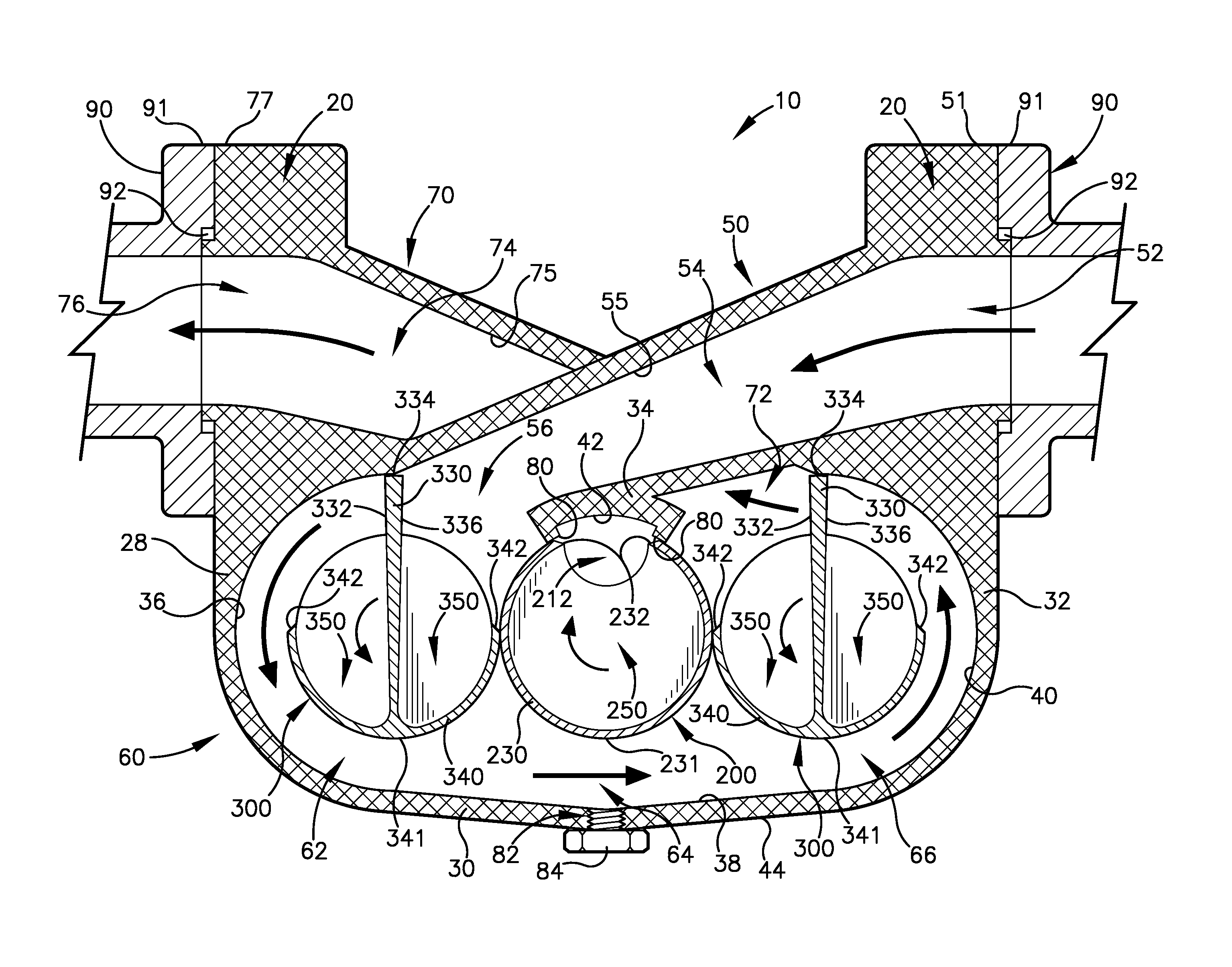
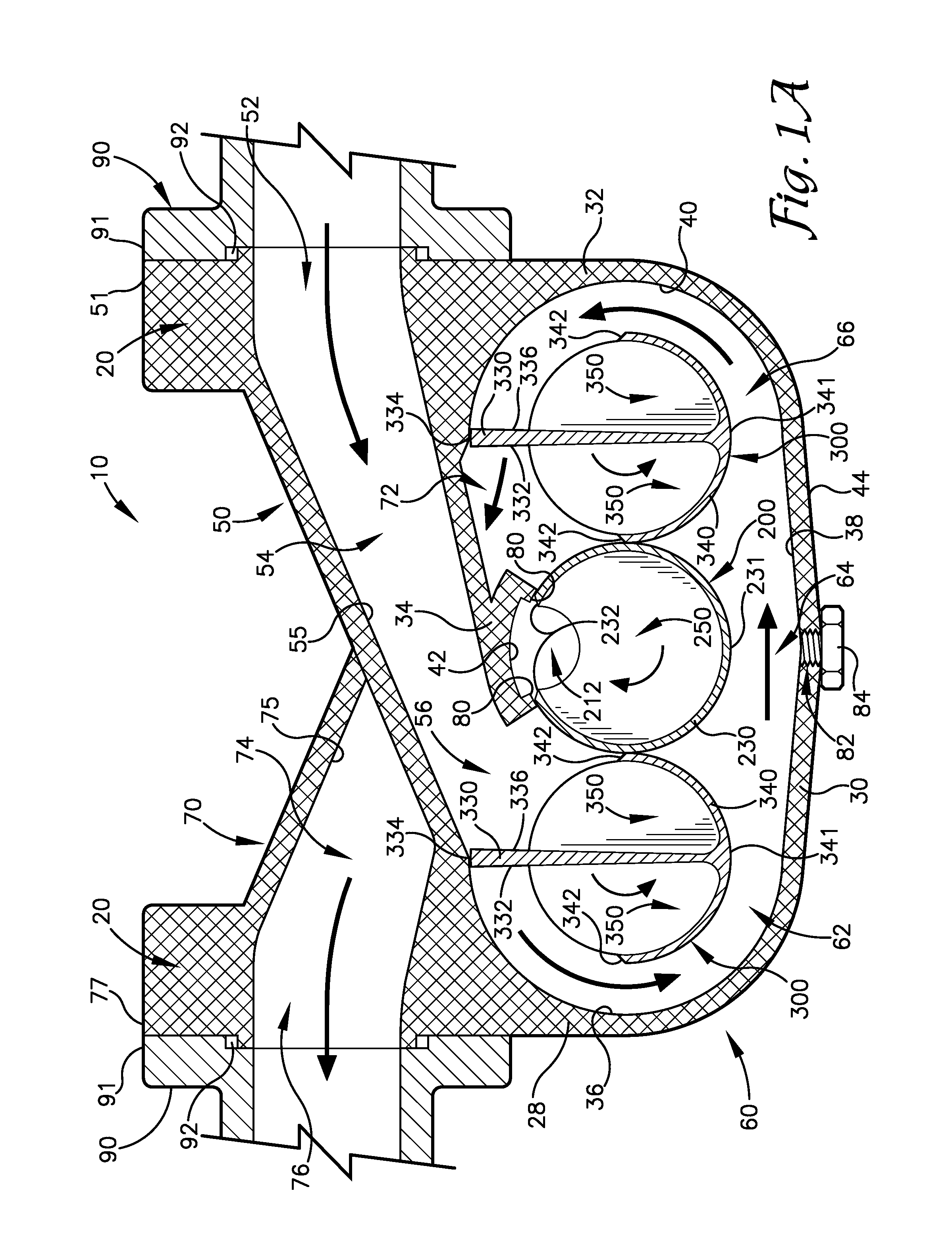
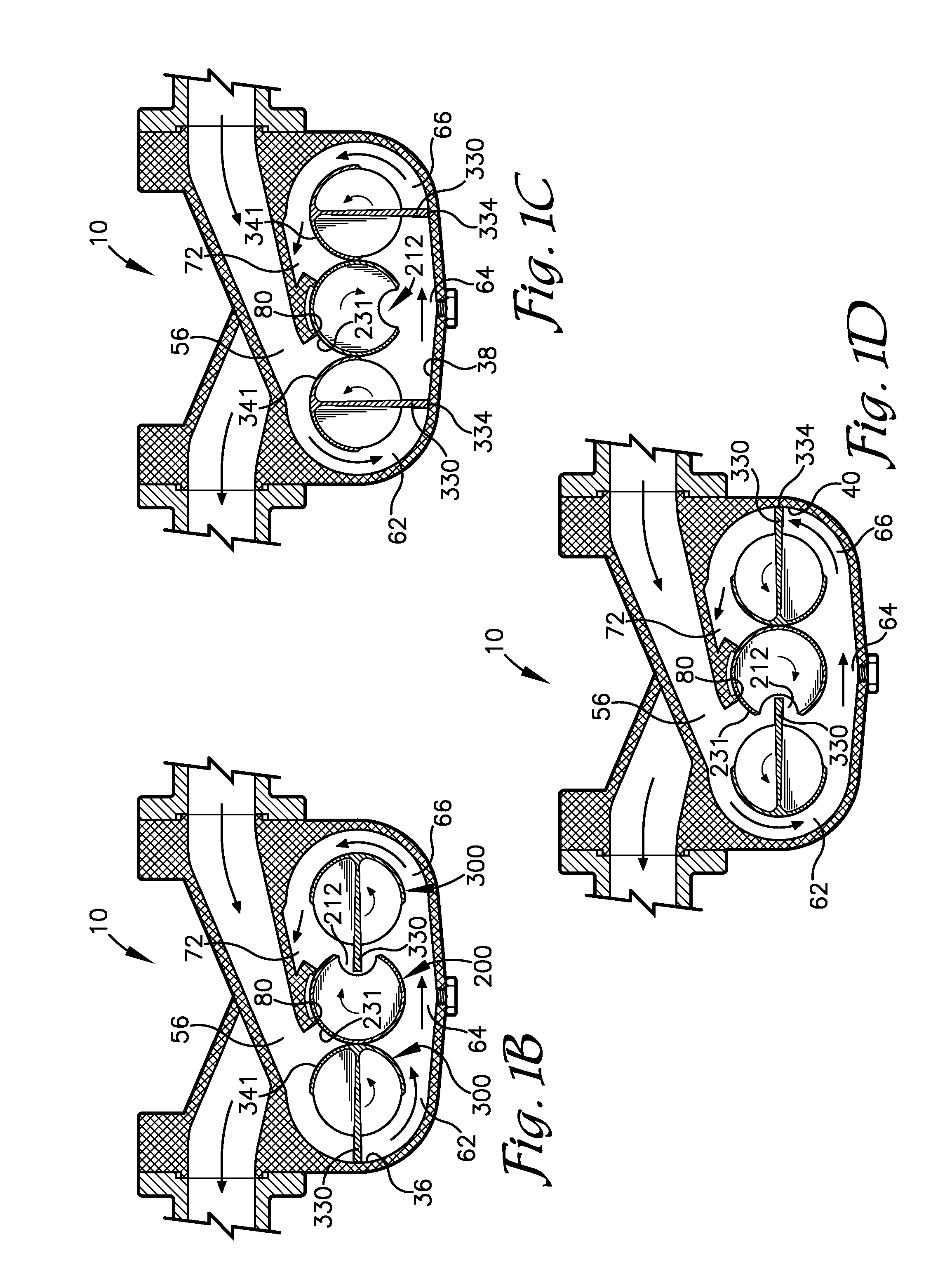
[0067]First referring to FIGS. 1A and 2, a flowmeter 10 according to one embodiment as shown. The flowmeter 10 comprising a housing or casing 20, an inlet 50, a fluid chamber 60, and an outlet 70. The housing 20 is comprised of an end wall 22, a plurality of hole 24, bolt(s) 26, a side wall 28, a bottom wall 30, a side wall 32, a top wall 34, a side interior surface 36, a bottom interior surface 38, a side interior surface 40, and a top interior surface 42.

[...


PUM


Abstract

A rotary positive displacement flowmeter of the type utilizing two displacement rotors and a blocking rotor with the blocking rotor having a single recess and the displacement rotor cylinders being of substantially similar size as the blocking rotor, resulting in a uniform flowpath through the flowmeter with alignment of the rotor axes in a 180 degree plane.

Description

FIELD OF THE INVENTION[0001]The present invention relates to flowmeters, and more particular to rotary positive displacement flowmeters utilizing multiple displacement rotors and a blocking rotor.BACKGROUND OF THE INVENTION[0002]Positive displacement flowmeter are well known in the art. Specifically, such a device is used in various applications within widespread industries, including the petrochemical and natural gas industries. The general purpose of a flowmeter is to measure the quantity of a substance, typically a gas or a liquid, flowing through the meter such that the amount of the substance can be readily and accurately determined.[0003]Typically, a substance flows through a conduit or line designed to move the substance from one point to another. Where applicable, the conduit is separated and a flowmeter is attached and, in many instances, the entire flow path of the substance is then diverted through the flowmeter. The movement of the substance through the flowmeter causes ...

Claims


Application Information

Patent Timeline
IPC IPC(8): G01F3/08
CPCG01F3/08G01F3/06
Inventor HERR, VINCE
Owner ADVANCED FLOW SOLUTIONS INC
Why Eureka
Try Eureka