Method for reducing energy consumption in a process to purify styrene monomer

Active Publication Date: 2015-11-26
TECH PRECESS TECH INC
View PDF6 Cites 2 Cited by
  • Summary
  • Abstract
  • Description
  • Claims
  • Application Information

AI Technical Summary

Benefits of technology

[0014]In general, this invention comprises a cascaded arrangement of two distillation processes whereby heat contained in the overhead vapor stream of one distillation process is utilized to reboil the entire bottoms liquid or a portion of the bottoms liquid of a second distillation process. More specifically, this invention is directed to a process for distilling benzene and toluene from ethylbenzene in one distil

Problems solved by technology

Overall the distillation process requires a large amount of energy (steam) to purify the styrene product.
Moreover, the separation by distillation of the styrene monomer (SM) from the unreacted ethylbenzene (EB) presents a considerably difficult problem due primarily to their close similarity in volatility.
In this regard, the boiling points of ethylbenzene and styrene are within approximately 10° C. of each other at 760 mm Hg, which makes separation by fractional distillation difficult and costly.
Conventionally, this EB/SM

Method used


Image

  • Method for reducing energy consumption in a process to purify styrene monomer
  • Method for reducing energy consumption in a process to purify styrene monomer
  • Method for reducing energy consumption in a process to purify styrene monomer

Examples


example 14

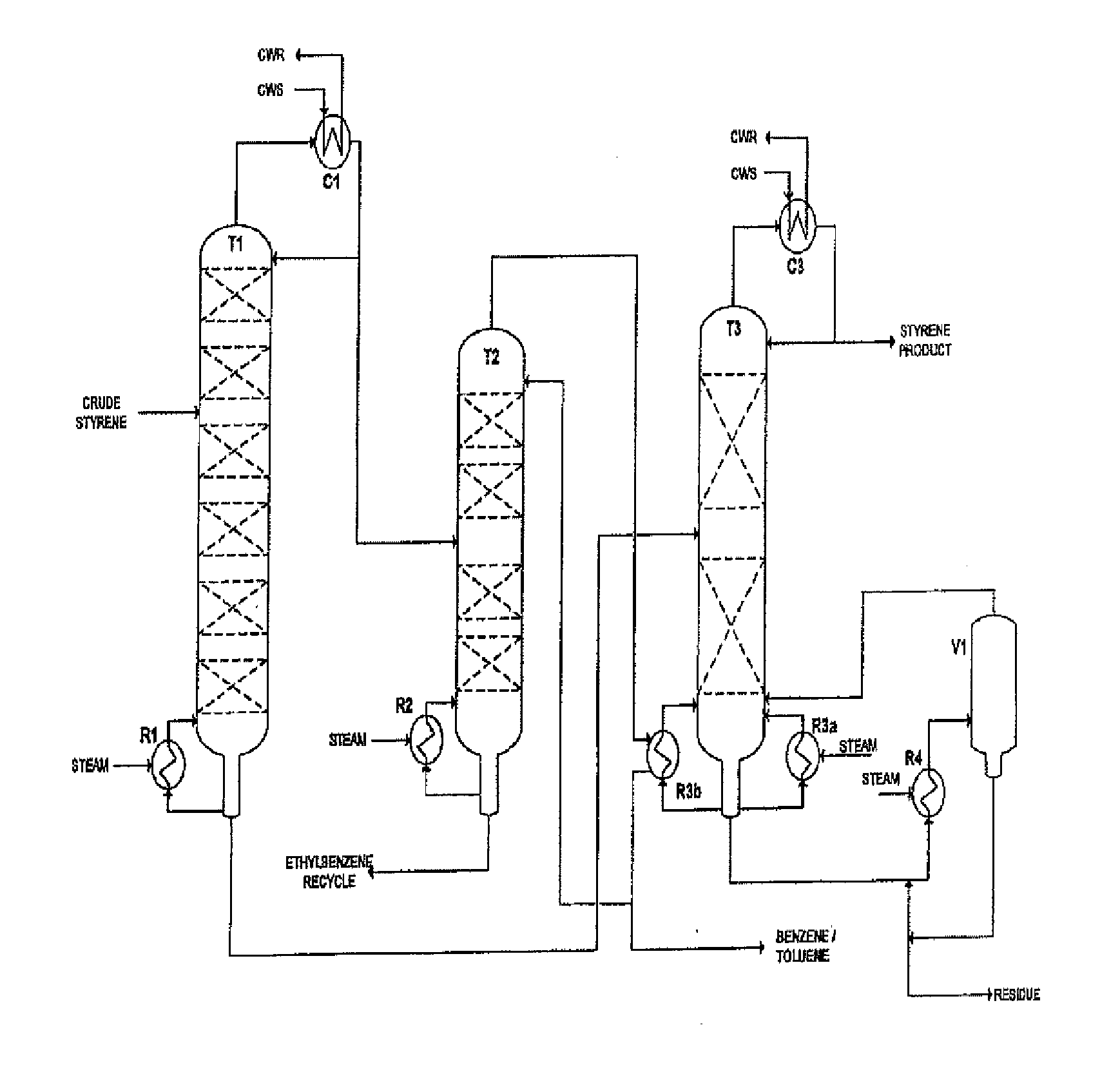
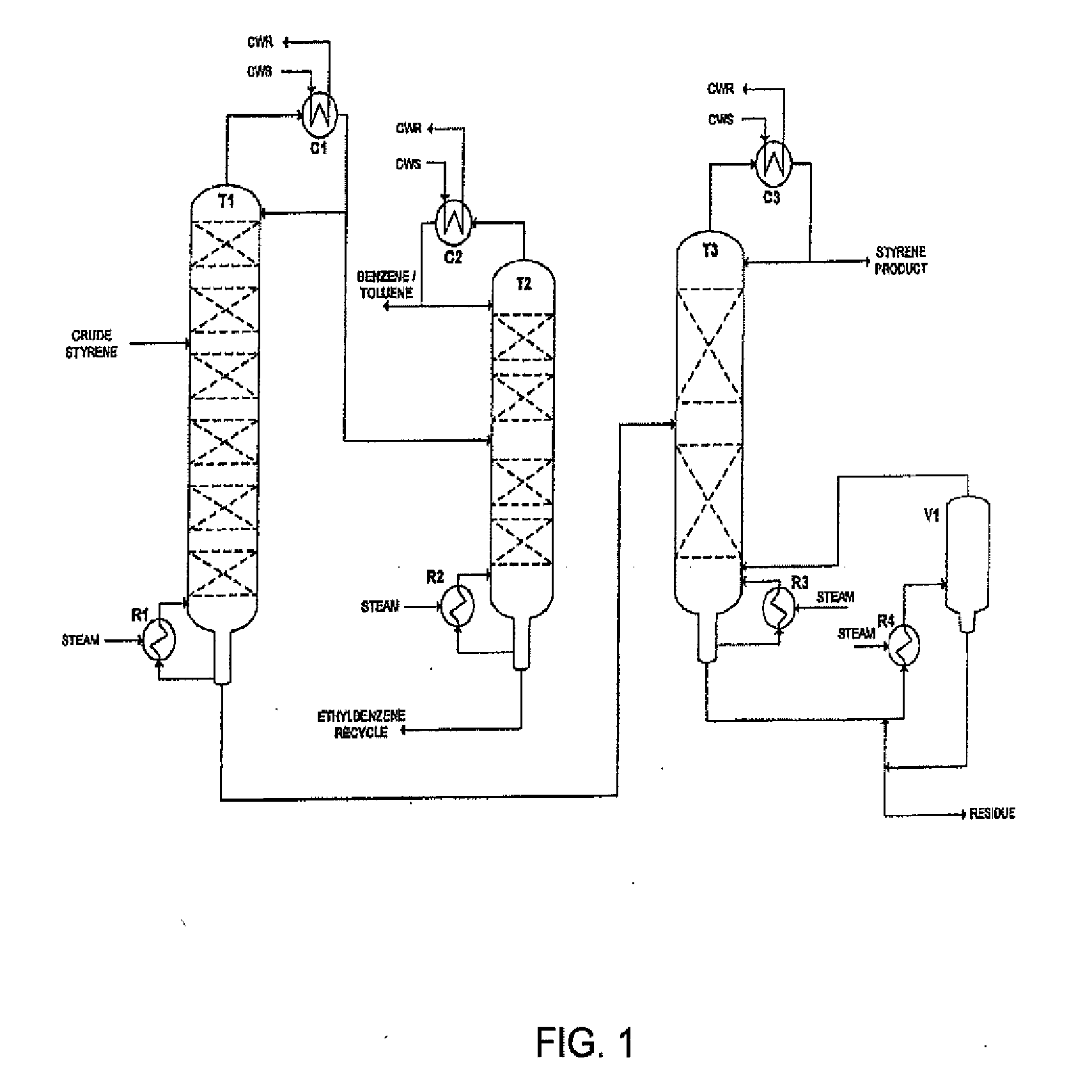
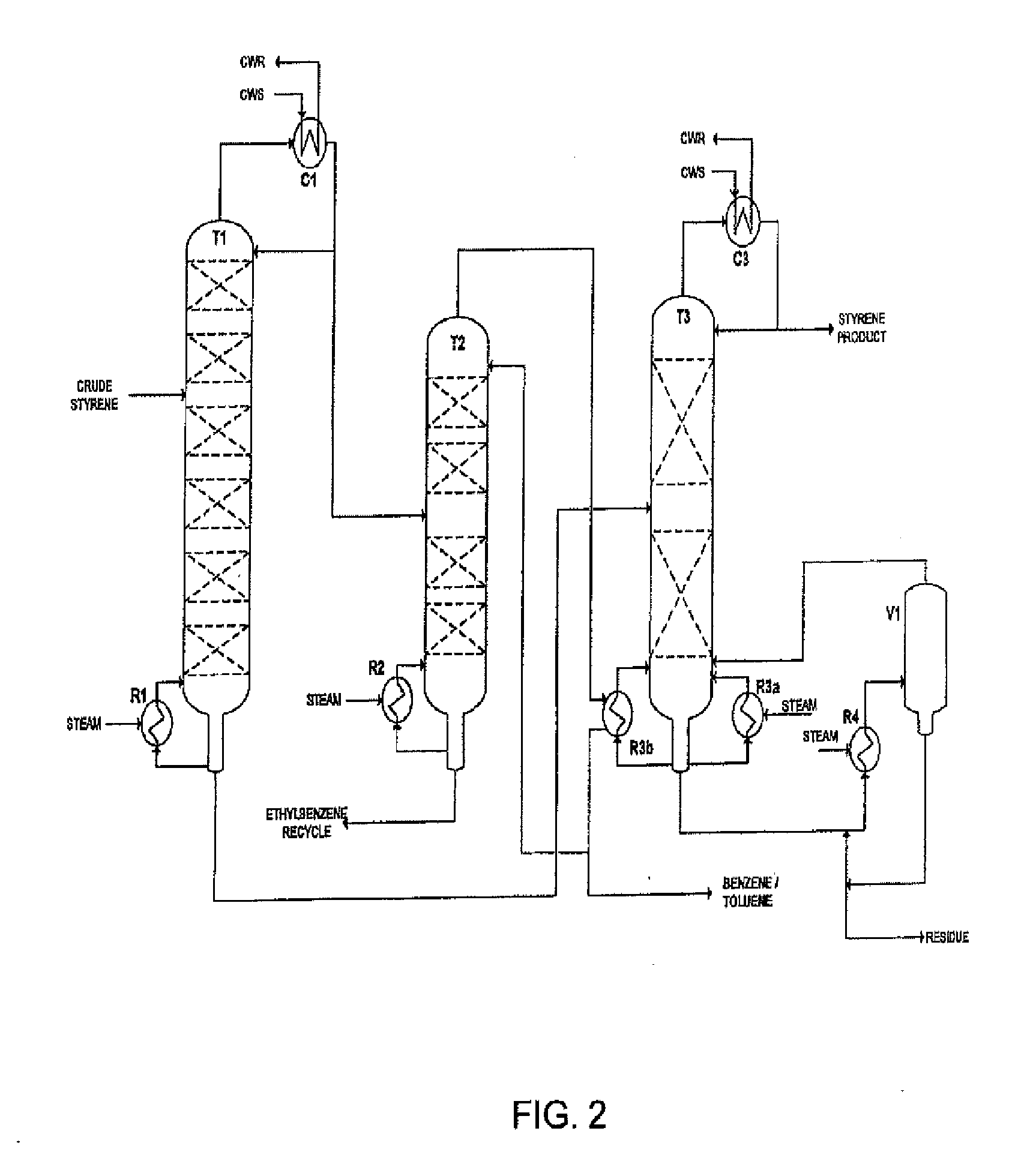
[0053 represents the upper limit of operating conditions for benzene / toluene column T2 and styrene finishing column T3, with trays as internals for both columns and a 15° C. temperature approach in styrene finishing column reboiler R3b.

[0054]The amount of heat that can be recovered by finishing column reboiler R3b depends on several parameters including but limited to, the number of theoretical stages (NTS) in benzene / toluene column T2, the number of theoretical stages in the styrene finishing column T3, operating pressures, concentration of toluene in the bottoms of the benzene / toluene column T2, the concentration of ethylbenzene in the overheads of the benzene / toluene column T2, the recovery of styrene in the styrene finishing column T3, and concentration of AMS in the distillate of styrene finishing column T3.

[0055]Table 3 presents Example 5 from Table 2, which is compared to Examples 15-24 having variations of the some of the above mentioned parameters.

TABLE 3Effect of various ...

example 23

[0066, the number of theoretical stages (NTS) in benzene / toluene column T2 is increased by 18. This change has a similar affect as the increase in toluene concentration allowed in the bottoms of benzene / toluene column T2 in Example 18. Adding more NTS to benzene / toluene column T2 made the separation of benzene and toluene from ethylbenzene slightly easier, and therefore lowered the reflux rate and decreased the amount of overhead vapor to supply duty to styrene finishing column reboiler R3b.

[0067]Example 24, the number of theoretical stages (NTS) in benzene / toluene column T2 is increased by 6. This change has a similar affect as the decrease in toluene concentration allowed in the bottoms of benzene / toluene column T2 in Example 17. Adding more NTS to benzene / toluene column T2 made the separation of benzene and toluene from ethylbenzene slightly harder, and therefore, increased the reflux rate and decreased the amount of overhead vapor to supply duty to styrene finishing column rebo...


PUM

PropertyMeasurementUnit
Fractionaaaaaaaaaa
Pressureaaaaaaaaaa
Pressureaaaaaaaaaa

Abstract

An energy conservation process directed to the purification of styrene monomer via distillation after the dehydrogenation reaction of ethylbenzene to produce crude styrene is disclosed. As practiced today, the purification of styrene via distillation requires large amount energy (i.e., steam) to provide heat to the various distillation columns. The presently disclosed improved process allows for a reduction in the amount of steam needed for this purpose.

Description

TECHNICAL FIELD[0001]This invention relates to energy-consumption improvements in processes to purify styrene monomer.BACKGROUND[0002]The majority of styrene monomer produced commercially is prepared by the dehydrogenation of ethylbenzene in a vapor phase, fixed catalyst-bed reactor. Each pass through the reactor converts about 60 to 75% of the ethylbenzene feed to styrene. The dehydrogenation reaction of ethylbenzene yields a crude styrene stream which is a mixture containing substantial portions of styrene and ethylbenzene as well as smaller amounts of reaction by-products and impurities, such as, benzene, toluene, alpha-methyl styrene (AMS) and heavies. To produce saleable styrene monomer product, the non-styrene components must be separated from the styrene product via distillation. Styrene monomer must be purified to a concentration of at least 99% by weight before it can be used by downstream polymer processes. The main components to be separated from styrene in the purificati...

Claims


Application Information

Patent Timeline
IPC IPC(8): C07C5/333C07C7/04
CPCC07C7/04C07C5/333C07C5/327C07C15/46
Inventor WELCH, VINCENT
Owner TECH PRECESS TECH INC
Why Eureka
Try Eureka