
Detecting of faults in a valve system and a fault tolerant control

a valve system and fault detection technology, applied in the direction of fluid couplings, servomotors, couplings, etc., can solve problems such as inability to detect faults

Inactive Publication Date: 2009-05-07
ROBERT BOSCH GMBH
View PDF4 Cites 27 Cited by
  • Summary
  • Abstract
  • Description
  • Claims
  • Application Information

AI Technical Summary

Benefits of technology

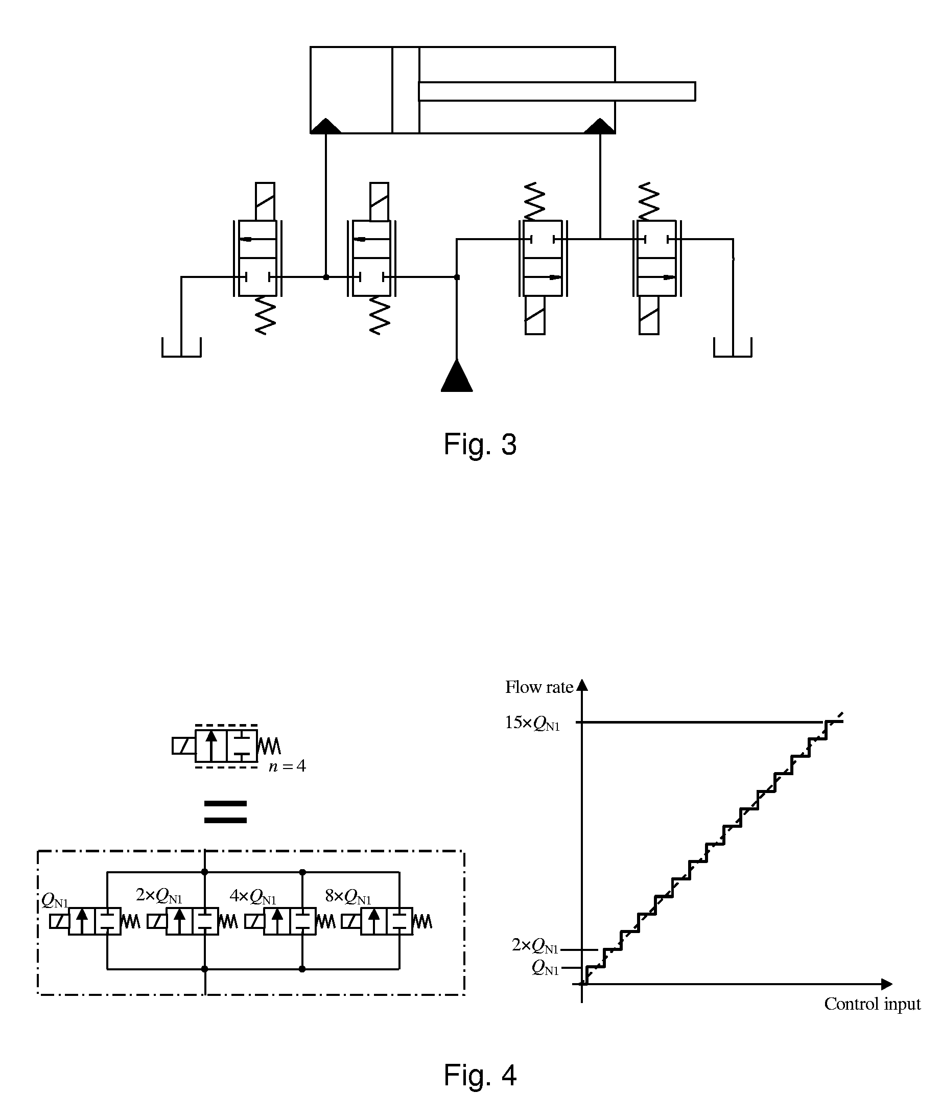
[0017]The greatest advantage of the presented system is that a fault in a valve does not prevent the operation of the system. If a valve is jammed fully open or remains partly open (table B, cases II to V), the reprogramming of the controller for the part of a single valve series may no longer be a sufficient measure. It is an advantage of the invention that the fault can be compensated for by using “extra” valve series. The valve series needed for the compensation are ready in the system which comprises four control edges. Other advantages include, for example, the fact that the system can be tested also under a load, and the actuator does not necessarily move at all during the tests. The effect of the faulty valves on the operation of the system can also be determined without using expensive and space consuming flow rate sensors. Typically, the pressure sensors are provided ready in the system. The sensors are used, for example, to monitor the pressures pA, pB, pP and pT, and they are also used for fault analysis.
that the fault can be compensated for by using “extra” valve series. The valve series needed for the compensation are ready in the system which comprises four control edges. Other advantages include, for example, the fact that the system can be tested also under a load, and the actuator does not necessarily move at all during the tests. The effect of the faulty valves on the operation of the system can also be determined without using expensive and space consuming flow rate sensors. Typically, the pressure sensors are provided ready in the system. The sensors are used, for example, to monitor the pressures pA, pB, pP and pT, and they are also used for fault analysis.

Problems solved by technology

In conventional arrangements, this is not possible without duplicating the valve and isolating the faulty valve from the rest of the system.
Also in the second example, the utilization of too large an opening is intentional, because it is not possible to find a correct or suitable smaller opening.

Method used


Image

  • Detecting of faults in a valve system and a fault tolerant control
  • Detecting of faults in a valve system and a fault tolerant control
  • Detecting of faults in a valve system and a fault tolerant control

Examples


case ii

[0038]In case II, the valve is jammed in the open position. The opening combinations are:

AV=[010101011111111100001111]

[0039]In the case III, the valve is jammed in a position x between the open and closed positions. The opening combinations are:

AV=[01010101xxxxxxxx00001111]

[0040]In case IV, the valve operates in such a way that it can be closed but it will not open fully. The opening combinations are:

AV=[0101010100xx00xx00001111]

[0041]In case V, the valve opens normally but cannot be closed fully. The opening combinations are:

AV=[01010101xx11xx1100001111]

[0042]In case VI, the valve changes its state but will not open or close fully. The opening combinations are:

AV=[01010101xxyyxxyy00001111]

[0043]In a corresponding manner, it is possible to form all the opening combinations if the first or third valve is faulty, or if several valves are faulty at the same time.

[0044]All the possible flow rates of the DFCU can be calculated by the formula:

Q=AVT[κ1κ2κ3]Δp

in which κ1, κ2 and κ3 are the ...


PUM


Abstract

In a method for controlling a valve system controlling an actuator, the first direction of motion of the actuator is controlled solely by the first and the second valve series; or, its second direction of motion is controlled solely by the third and the fourth valve series; and an error caused by a fault situation in the control of the actuator is compensated for by using, for the control of the first direction of motion, also the third valve series, the fourth valve series, or both of them; or, an error in the control of the actuator caused by a fault situation is compensated for by using, for the control of the second direction of motion, also the first valve series, the second valve series, or both of them. In the method, for searching for faults in the valve system controlling the actuator, the pressure of the inlet port of the valve system, the pressure of the first working port, and the pressure of the outlet port are determined; one or more valves of the first valve series and one or more valves of the second valve series are opened; the measured pressure of the first working port is compared with a situation corresponding to a system operating correctly; and on the basis of the comparison it is concluded whether the single valve is faulty or not.

Description

FIELD OF THE INVENTION[0001]The invention relates to a method for controlling a valve system controlling an actuator. The invention relates to a method for testing faults in a valve system controlling an actuator. The invention also relates to a valve system for the control of an actuator.BACKGROUND OF THE INVENTION[0002]In hydraulics, power is transmitted by means of pressure and volume flow. Normally, the volume flow is generated by a pump, and the resistance caused by the system increases the pressure. Normally, the aim is to move actuators, such as cylinders and motors, by means of the volume flow and the pressure. Because the actuators must normally be moved in both directions, either back and forth or changing the direction of circulation, and possibly even be stopped, valves are needed for controlling the volume flow. When the actuators are to be moved precisely, for example at a specific rate, accurate valves are needed to control the volume flow. Conventionally, such valves...

Claims


Application Information

Patent Timeline
IPC IPC(8): F15B13/00F15BF15B11/00F15B19/00F15B20/00
CPCF15B11/006F15B11/0426F15B19/005F15B20/008F15B2211/8752F15B2211/40507F15B2211/40592F15B2211/411F15B2211/8636F15B2211/30575Y10T137/86493Y10T137/0318F15B20/00
Inventor SIIVONEN, LAURILINJAMA, MATTI
Owner ROBERT BOSCH GMBH
Learn More