Robot

a robot and robot technology, applied in the field of robots, can solve the problems of limited robot movable range, difficult robot to see a high position as seen from the robot, and the limitations of the conventional technology described abov

Inactive Publication Date: 2009-05-07
HITACHI LTD
View PDF13 Cites 36 Cited by
  • Summary
  • Abstract
  • Description
  • Claims
  • Application Information

AI Technical Summary

Benefits of technology

[0016]It is therefore an object of the invention to provide a robot wherein a capable, compact, and movable image pickup device is installed in the head of the robot in order to ensure execution of traveling, and operation with reliability.
[0018]With the aspect of the invention, it is possible to observe a wide range from a visual field in a high position to a visual field oriented in a direction directly below, and operations for traveling and transportation of objects can be safely executed with reliability.

Problems solved by technology

Conventional technologies described as above have had difficulties in meeting those requirements.
With the conventional technologies, the camera are at a low position all the time, so that it has been difficult for the robot to see a high position as seen from the robot, such as the top of the desk.
With a technology described in Patent document 1, the head of the robot, in whole, is moved, however, there is a limitation to a movable range of the robot, in a downward direction, because a lower part of the head comes into contact with the neck of the robot, so that it has been difficult to sufficiently obtain the visual field oriented in the direction directly below.
Further, with a technology described in Patent document 2, the head in whole travels forward when the robot looks in a downward direction, so that it has been difficult for the robot to keep itself in balance.

Method used


Image

  • Robot
  • Robot
  • Robot

Examples


Embodiment Construction

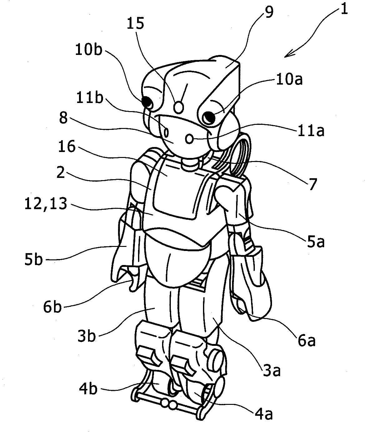
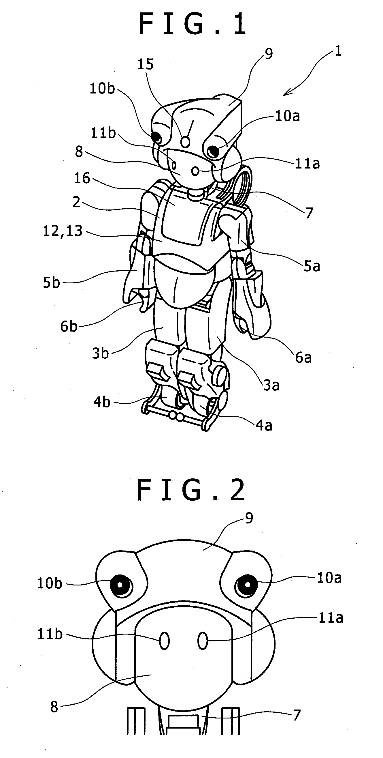
[0027]FIG. 1 shows an external view of a robot according to one embodiment of the invention. In this connection, a humanoid robot is described hereinafter as a robot according to the present embodiment of the invention by way of example, however, it is to be pointed out that the invention is not limited thereto. Further, a camera is described hereinafter as a movable image pickup device according to the present embodiment of the invention by way of example, however, it is to be pointed out that the invention is not limited thereto.

[0028]A robot 1 includes a trunk 2 as a main body, leg mechanisms 3a, 3b for causing the robot to travel, provided in a lower part of the trunk 2, and arms 5a, 5b, attached to upper parts of the trunk 2, respectively. Wheels 4a, 4b are installed at respective extremities of the leg mechanisms 3a, 3b. Further, hands 6a, 6b are installed at respective extremities of the arms 5a, 5b. A battery 12 for driving the robot 1, and a controller 13 are mounted in the...


PUM


Abstract

Described herein is a robot having a camera mount that is movable along a curved surface of an upper part of the head, on a front side thereof, and two units of cameras that are mounted in the camera mount. The cameras are disposed such that the cameras are laterally separated from each other at an interval substantially equivalent to a lateral width of the head, respective extremities of the cameras are substantially flush with the front end of the head, and the cameras are positioned in close proximity of the upper end of the robot.

Description

BACKGROUND OF THE INVENTION[0001]1. Field of the Invention[0002]The invention relates to a robot, and in particular, to a robot with a camera mounted therein.[0003]2. Description of the Related Art[0004]There have since been developed a robot capable of traveling among human beings at home, in the office, and in public space, and so forth to provide various services such as transportation of objects, and so forth. The robot is mostly provided with a camera, a sensor, and so forth, mounted in an upper part of a main body thereof, for collection of information, and in the case of an anthropomorphic robot, the camera, sensor, and so forth are mostly mounted in the head of the robot.[0005]It has been well known that the robot is provided with a mechanism for moving the head with a camera mounted therein, in whole, or the camera mounted in the head, in order to widen an image-pickup range of the camera mounted in the robot.[0006]In Patent document 1, there has been disclosed the head of ...

Claims


Application Information

Patent Timeline
Patent Type & Authority Applications(United States)
IPC IPC(8): B25J19/04
CPCB25J19/023B25J5/00B25J9/0006B25J11/0085B25J19/04
Inventor EGAWA, SAKUNAKAMURA, RYOSUKEAMINO, AZUSATAMAMOTO, JUNICHIYANAGIMOTO, MANABU
Owner HITACHI LTD
Why Eureka
Try Eureka