Patient Monitoring

a patient monitoring and patient technology, applied in the field of patient monitoring, can solve the problems of unproven use of some aspects of hemodynamic monitoring, and achieve the effect of improving the hemodynamic status of the subject and restoring the hemodynamic status

Active Publication Date: 2009-05-21
MASIMO CORP +1
View PDF10 Cites 60 Cited by
  • Summary
  • Abstract
  • Description
  • Claims
  • Application Information

AI Technical Summary

Benefits of technology

[0015]The invention relates to improved hemodynamic monitors. In particular, the invention relates to monitors which provide the carer for a subject with readily interpretable data to improve interventions aimed at restoring the hemodynamic status of the subject.

Problems solved by technology

Care 2005, 566-572), yet the utility of some aspects of hemodynamic monitoring is unproven.

Method used


Image

  • Patient Monitoring
  • Patient Monitoring
  • Patient Monitoring

Examples


Embodiment Construction

Brief Description of the Figures

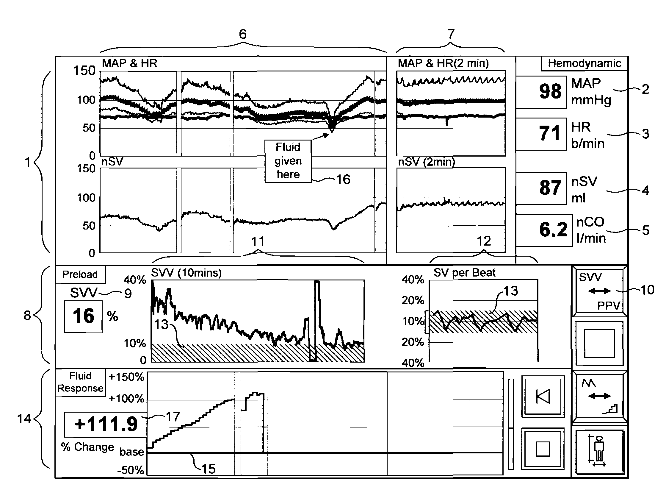
[0111]FIG. 1 is a representation of an exemplary display means of the invention.

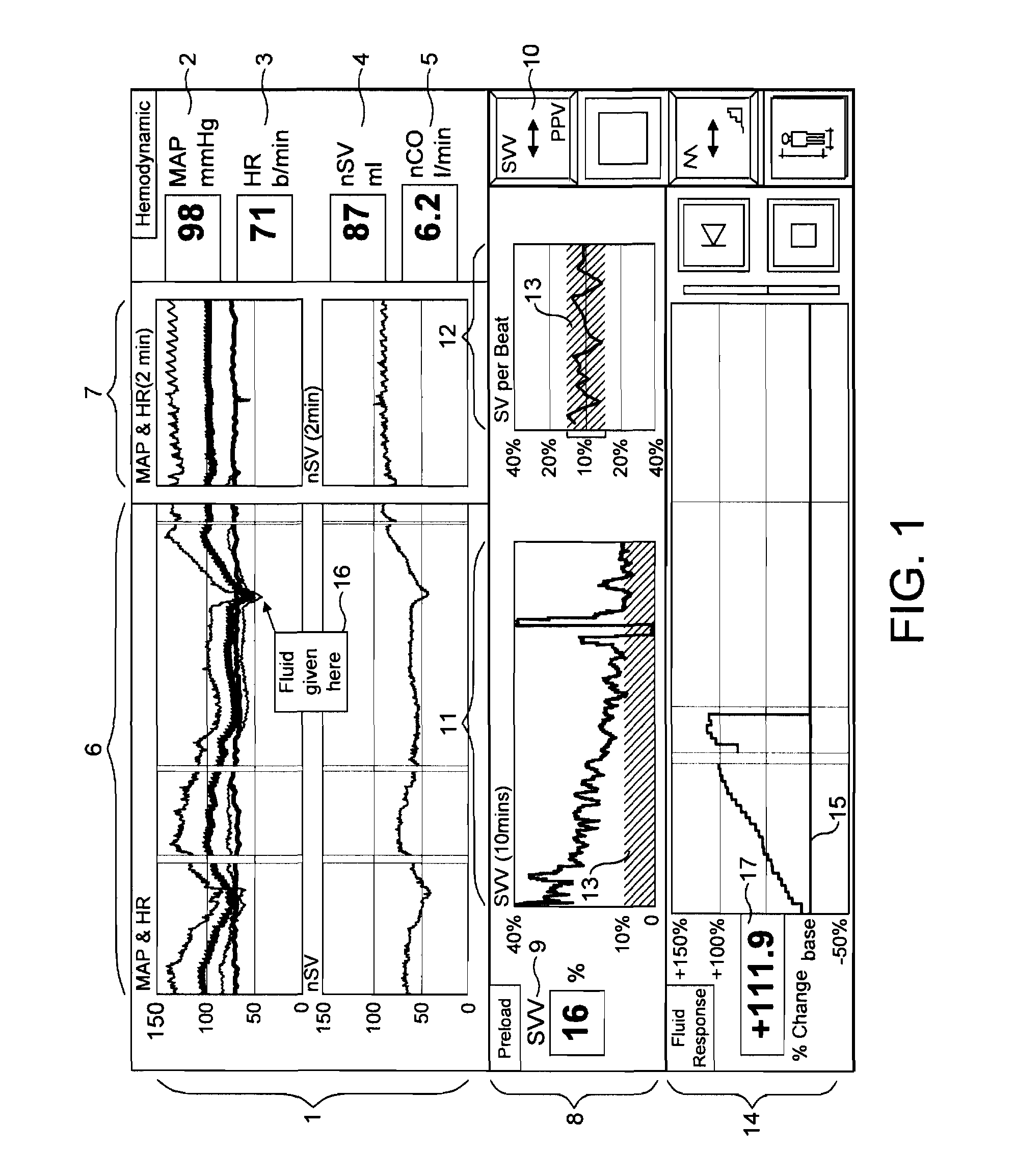
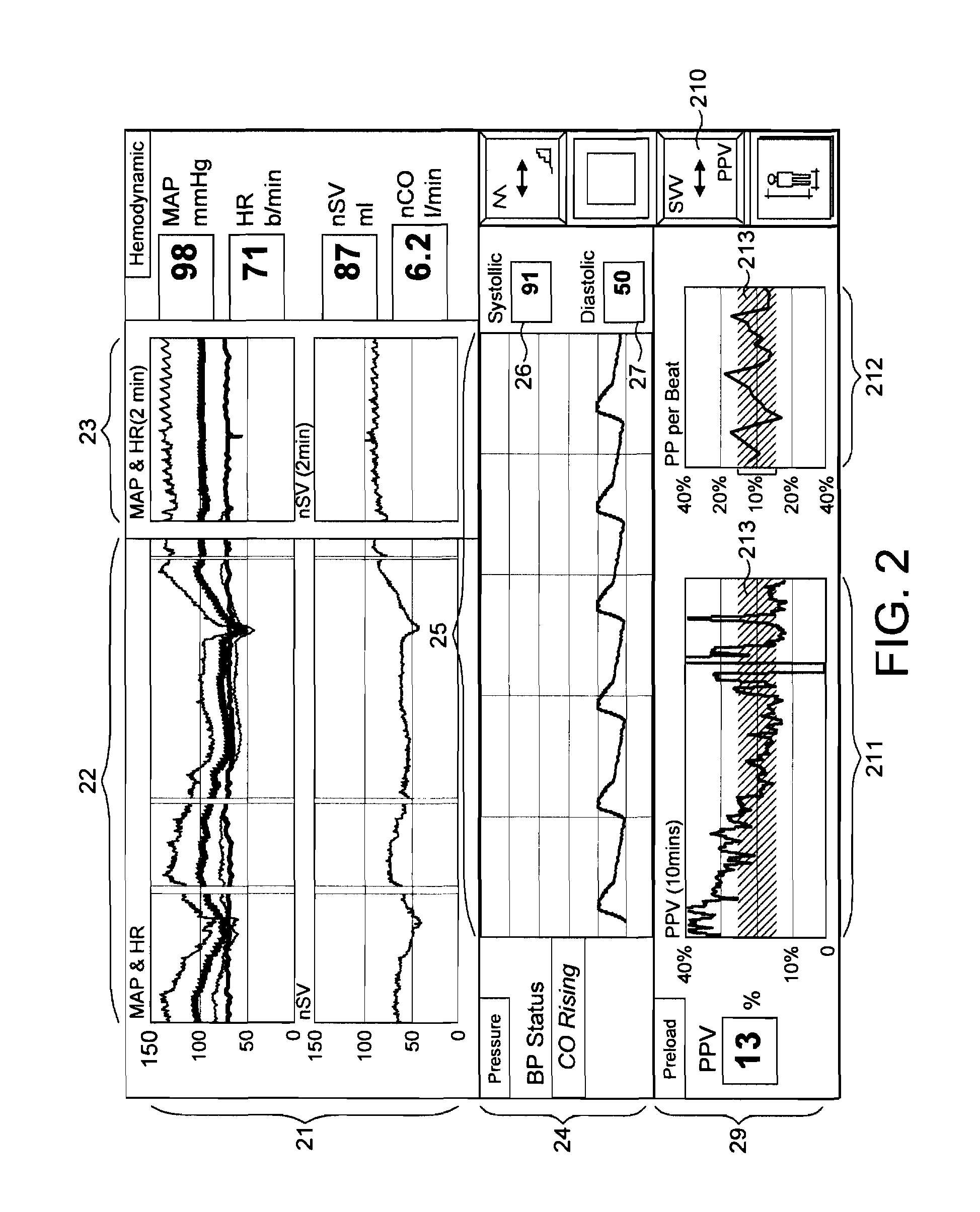
[0112]FIG. 2 is a representation of another display means of the invention, incorporating a display of raw analogue blood pressure data.

[0113]FIG. 3 is a flow chart showing the data handling and processing steps for generation of the display.

[0114]FIG. 4 shows an example of the fluid responsiveness display which forms an integral part of the monitors of the invention.

[0115]FIG. 5 shows an example of the fluid responses display incorporating a trend display of SVV and an acute changes display of respiratory variation in SV. Raw analogue blood pressure is also displayed as an additional signal quality indicator.

[0116]FIG. 6 is a further representation of the display means of the monitors of the invention.

[0117]As shown in FIG. 1, the display means is a flat screen panel and incorporates an upper panel of images (1) displaying the following stress related hemodynamic paramete...


PUM


Abstract

A hemodynamic monitor and corresponding method for determining the requirement for, and if required the nature or extent of, and for monitoring the response to, an intervention by a carer for a subject in order to improve the hydration level and hemodynamic status of the subject during a period or periods of hemodynamic instability includes, firstly, a processor. The processor incorporates software arranged to continuously analyse and process a blood pressure or arterial volume / plethysmographic signal obtained from the subject in order to derive a plurality of complementary parameters throughout the monitoring of the subject. The monitor also incorporates display means displaying images representing the derived plurality of complementary parameters. The images may include at least one image representing graphically at least one stress related hemodynamic parameter plotted against time to provide an immediate indication of a change in hemodynamic status and thus the requirement for an intervention. The images may also include at least one image representing graphically at least one fluid responsiveness parameter plotted against time to provide an indication of the hydration level and associated ventricular pre load status of the subject to determine the nature or extent of the intervention if required. Respiratory variations in fluid responsiveness parameters may usefully be displayed. The images may also include at least one image representing graphically at least one response related parameter compared to the value of the parameter at the point of the intervention to provide an indication of the desired and / or actual response of the subject to an intervention. Trend and acute changes displays may be combined. Specific parameters providing information on the quality of the left ventricle and right heart / venous return / preload may also be derived and displayed.

Description

CROSS-REFERENCE TO RELATED APPLICATIONS[0001]This application is a continuation-in-part of U.S. application Ser. No. 12 / 099,411, filed on Apr. 8, 2008, which claims the benefit under 35 U.S.C. § 119(e) to U.S. Provisional Application No. 60 / 960,720, filed on Oct. 11, 2007; the contents of which related applications are incorporated herein by reference in their entireties.FIELD OF THE INVENTION[0002]The present invention relates to improvements in patient monitoring and directing treatment. In particular, the invention relates to apparatus and methods for determining the requirement for, and / or if required the nature or extent of, and / or for monitoring the response to, an intervention by a carer for a subject in order to improve the hydration level and / or hemodynamic status of the subject. The apparatus and methods are particularly useful during a period or periods of hemodynamic instability, such as during a surgical procedure for example.BACKGROUND OF THE INVENTION[0003]Hemodynamic...

Claims


Application Information

Patent Timeline
Patent Type & Authority Applications(United States)
IPC IPC(8): A61B5/02
CPCA61B5/02028A61B5/0205A61B5/0215A61B5/022A61B5/743A61B5/029A61B5/0402A61B5/145G06F19/3406A61B5/024A61B5/742G16H40/63A61B5/318
Inventor O'BRIEN, TERENCE KEVINMILLS, ERIC STEPHEN
Owner MASIMO CORP
Why Eureka
Try Eureka