System and method for monitoring structures

Inactive Publication Date: 2009-05-21
SCHLUMBERGER TECH CORP
View PDF0 Cites 94 Cited by
  • Summary
  • Abstract
  • Description
  • Claims
  • Application Information

AI Technical Summary

Problems solved by technology

Changes in parameters can be indicative of problems or ...

Method used


Image

  • System and method for monitoring structures
  • System and method for monitoring structures
  • System and method for monitoring structures

Examples


Embodiment Construction

[0016]In the following description, numerous details are set forth to provide an understanding of the present invention. However, it will be understood by those of ordinary skill in the art that the present invention may be practiced without these details and that numerous variations or modifications from the described embodiments may be possible.

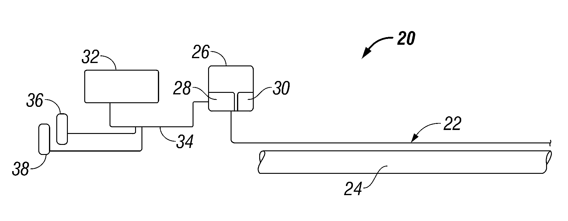
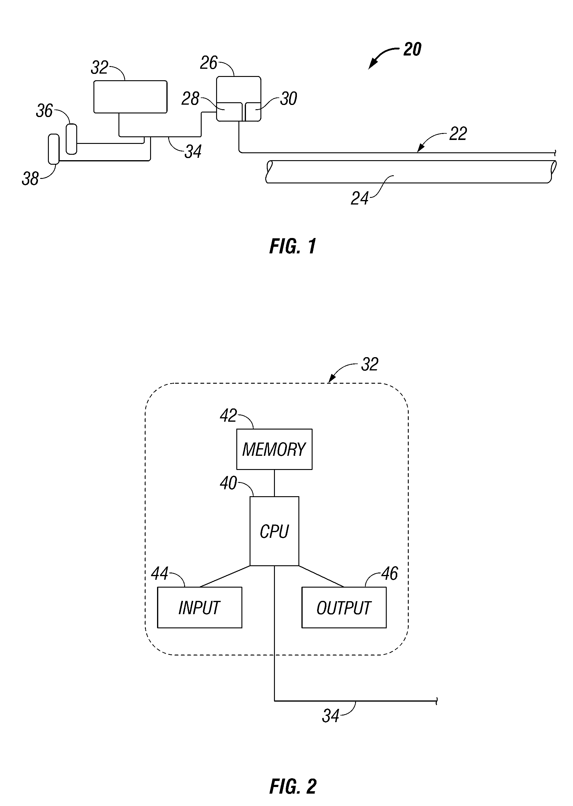
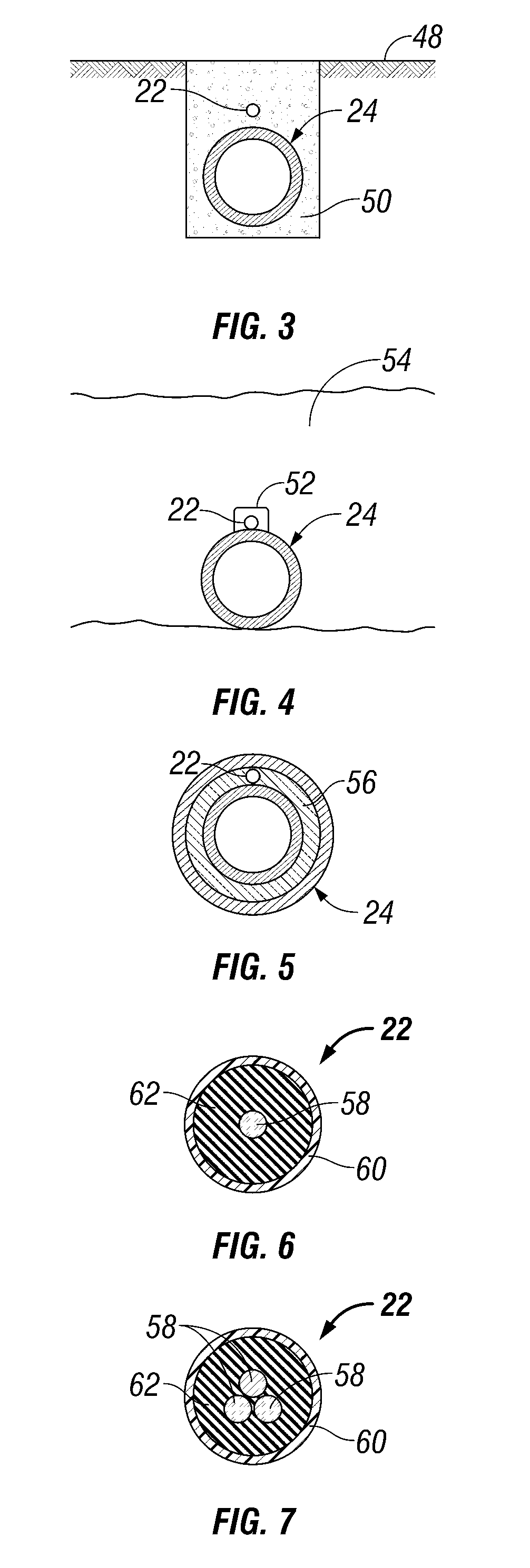
[0017]The present invention relates to a system and methodology for monitoring parameters along the length of elongate structures to determine problems or potential problems with the structures. For example, the system and methodology can be used to provide an indication of a problem or a potential problem with a pipeline or a power cable. Examples include the monitoring and detection of leaks and / or disturbances with pipelines that run through difficult terrain or through substantially inaccessible environments, e.g. pipelines buried within the earth or routed through subsea environments. The technique can also be used with subsea energy c...


PUM


Abstract

A technique facilitates the monitoring of elongate structures. An elongate structure is combined with an optical fiber deployed along the structure. An interrogation system is operatively joined with the optical fiber to input and monitor optical signals to determine any changes in parameters related to the structure.

Description

BACKGROUND OF THE INVENTION[0001]A variety of structures, e.g. pipelines, can extend over substantial distances and be relatively inaccessible, creating difficulties in monitoring such structures. For example, high-pressure gas pipelines can extend across inhospitable terrain that creates risks with respect to maintaining the integrity of the pipe. One risk is from ground movement, e.g. ground movement from landslides or seismic events, which can strain the pipeline beyond its design load. Additionally, there are risks from human intervention, including malicious acts, such as sabotage or theft of contents, or inadvertent acts, such as operation of earth moving equipment proximate the pipeline. Pipelines also can be susceptible to leaks caused by a variety of factors.[0002]With many types of pipelines or other elongate structures, the measurement of parameters indicative of problems or potential problems is difficult. For example, the measurement of strain, temperature, and other in...

Claims


Application Information

Patent Timeline
IPC IPC(8): G01L1/24G01L5/00
CPCG01D5/35303G01H9/004G01M11/086G01K11/32G01K1/143G01D5/35354G01D5/353G01L1/242G01M11/08
Inventor HARTOG, ARTHUR H.STRONG, ANDREWHILTON, GRAEMELEES, GARETH P.
Owner SCHLUMBERGER TECH CORP
Why Eureka
Try Eureka