Light source module, method for driving the light source module, display device having the light source module

a technology of light source module and light source module, which is applied in the direction of electric variable regulation, process and machine control, instruments, etc., can solve the problems of brightness spots, light source modules typically consume the most power of all the components of the display, and the contrast ratio of the display panel is degraded, so as to reduce brightness spots and maximize local relative contrast ratio

Inactive Publication Date: 2009-06-04
SAMSUNG DISPLAY CO LTD
View PDF4 Cites 59 Cited by
  • Summary
  • Abstract
  • Description
  • Claims
  • Application Information

AI Technical Summary

Benefits of technology

[0008]The present disclosure provides a light source module, a method for driving the light source module, and a display device having the light source module. The light source module performs brightness dimming on each light source bl

Problems solved by technology

This generally degrades the contrast ratio of the display panel.
When the display panel displays an all-black image, the light source module still generates light with uniform brightness and there is typically some light l

Method used


Image

  • Light source module, method for driving the light source module, display device having the light source module
  • Light source module, method for driving the light source module, display device having the light source module
  • Light source module, method for driving the light source module, display device having the light source module

Examples


Embodiment Construction

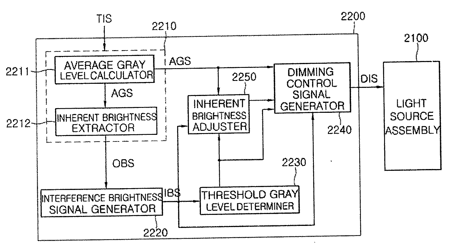
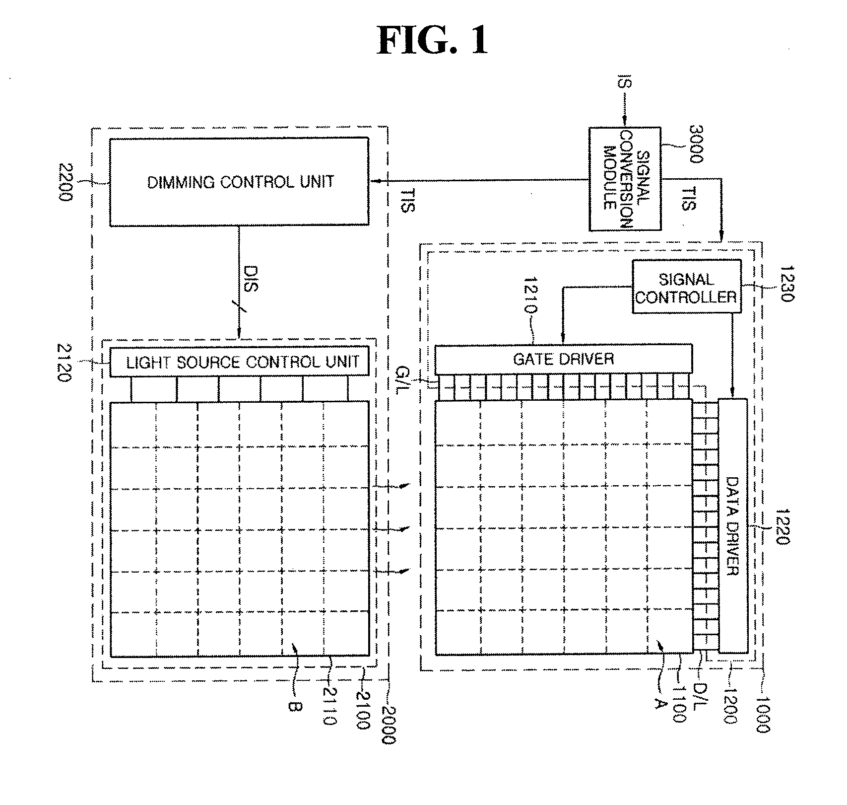
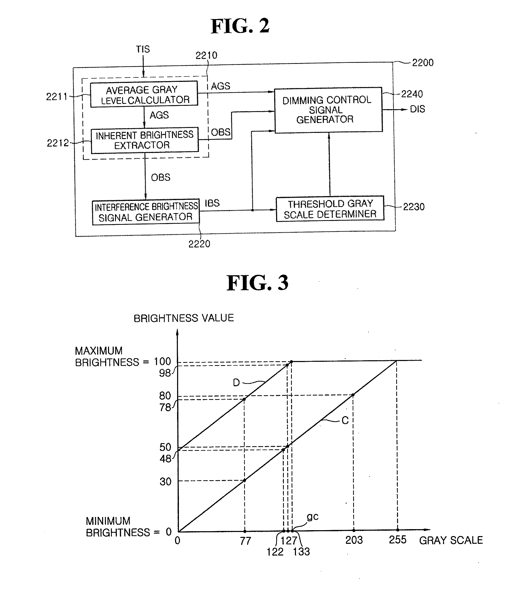
[0049]FIG. 1 is a block diagram of a display device in accordance with an exemplary embodiment. FIG. 2 is a block diagram of the dimming controller 2200 show in the display device of FIG. 1. FIG. 3 is a graph comparing brightness of a backlight block with gray levels of an image signal of the block in the display device of FIG. 1.

[0050]Referring to FIGS. 1 through 3, the display device in accordance with an exemplary embodiment includes a display panel 1000, a light source module 2000, and a signal conversion module 3000.

[0051]The signal conversion module 3000 converts an image signal IS input received from an external video card (not shown) and provides the converted image signal TIS, to the display panel 100 and to the light source module 2000. In this exemplary embodiment, the signal conversion module 3000 converts an image signal IS having a transition minimized differential signaling (TMDS) format into an converted image signal TIS having a low voltage differential signaling (L...


PUM


Abstract

A light source module having a plurality of light source blocks corresponding to a plurality of display regions, a method for driving the light source module, and a display device having the light source module. The output brightness of each of the light source blocks is individually dimmed according to a dimming control signal. A dimming control unit determines the average gray level and inherent brightness of each of the respective display regions, calculates a threshold gray level of each display region by using its inherent brightness, outputs a fixed brightness as a dimming control signal when the average gray level of the display region is greater than the threshold gray level, and outputs a variable brightness based upon the inherent brightness value, as the dimming control signal when the average gray level of the display region is less than the threshold gray level. Accordingly, brightness spots can be reduced by performing the brightness dimming with consideration of the interference brightness caused by the adjacent light source blocks.

Description

CROSS-REFERENCE TO RELATED APPLICATION[0001]This application claims priority, under 35 USC §119, to Korean Patent Application No. 10-2007-0124883 filed on Dec. 4, 2007, which is incorporated by reference in its entirety.BACKGROUND OF THE INVENTION[0002]1. Field of the Invention[0003]The present invention relates to a light source module, a method for driving the light source module, and a display device having the light source module, and more particularly, to a light source module divided into several regions for a display device, wherein brightness dimming is performed on each light source block depending upon the brightness of adjacent light source blocks.[0004]2. Description of the Related Art[0005]Generally, liquid crystal displays (LCDs), a type of flat display panels, contain liquid crystal pixels that are not self-luminous. Therefore a separate light source module (e.g., backlight unit) is one of the key components of a liquid crystal display (LCD). LCDs display an image by ...

Claims


Application Information

Patent Timeline
IPC IPC(8): H05B41/36
CPCG09G3/3426G09G2320/0646G09G5/10H05B33/0824H05B33/0854G09G2360/16H05B45/10H05B45/44H05B45/12G02F1/133
Inventor PARK, MUN-SOO
Owner SAMSUNG DISPLAY CO LTD
Why Eureka
Try Eureka