
Locking Mechanism For Flooring Boards

a locking mechanism and flooring technology, applied in the field of wood flooring, can solve the problems of generating squeaking sound, affecting the stability of the floor,

Inactive Publication Date: 2009-06-18
LIU DAVID C
View PDF21 Cites 128 Cited by
  • Summary
  • Abstract
  • Description
  • Claims
  • Application Information

AI Technical Summary

Benefits of technology

[0007]The present invention provides an improved locking mechanism for joining floor boards. Each floor board is provided with a special profile that does not require precision milling and adjacent floor boards are joined by fitting them together thought the special profile and with use of a locking device. In one embodiment of the invention, there is provided a locking system for floor boards. The locking system comprises a plurality of floor boards and a plurality of locking devices. Each floor board has a top side, a bottom side, a first short side, a second short side, a first long side, and a second long side, each long side has a length. The first long side has a first tongue and a second tongue along the length of the first long side, the first tongue being defined by a first upper abutment surface and a first lower abutment surface, the second tongue being defined by a second upper abutment surface and a second lower abutment surface. The second long side has a third tongue and a first locking groove along the length of the second long side, the third tongue being defined by a third upper abutment surface and a third lower abutment surface, the first locking groove being defined by a first upper groove surface and the third upper abutment surface. Each

Problems solved by technology

Different systems have been used to ease construction of wood flooring; however, most of them present some deficiency especially in relation to engaging thin laminate “floating floor” surfaces.
However, the lock between two adjacent flooring panels sometime becomes “loose,” allowing some movement between the two flooring panels.
The movement between the adjacent flooring panels generates squeaking sound and it is hard to eliminate.
The lock also requires precision milling for the lock works properly and small deformation of flooring panel after milling will render the lock and locking device unusable.

Method used


Image

  • Locking Mechanism For Flooring Boards
  • Locking Mechanism For Flooring Boards
  • Locking Mechanism For Flooring Boards

Examples


Embodiment Construction

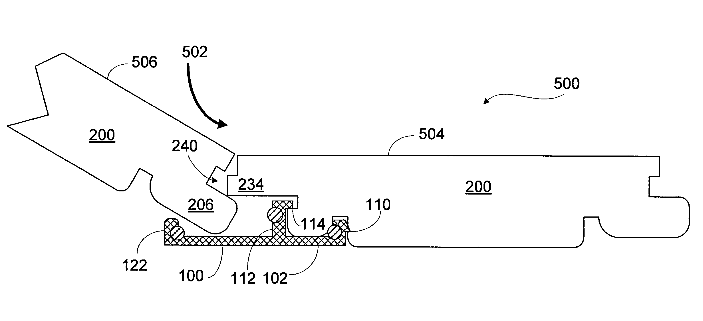
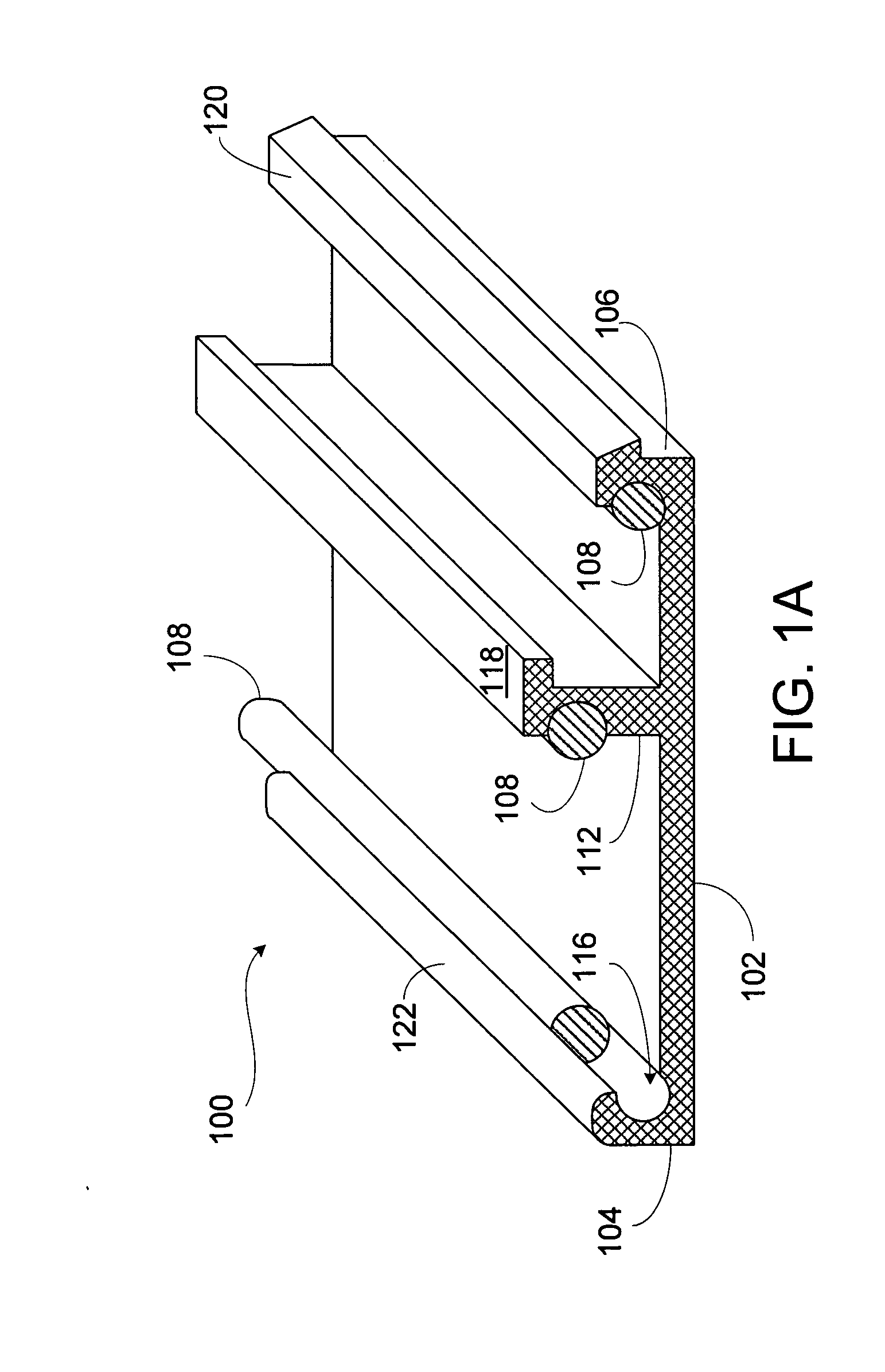
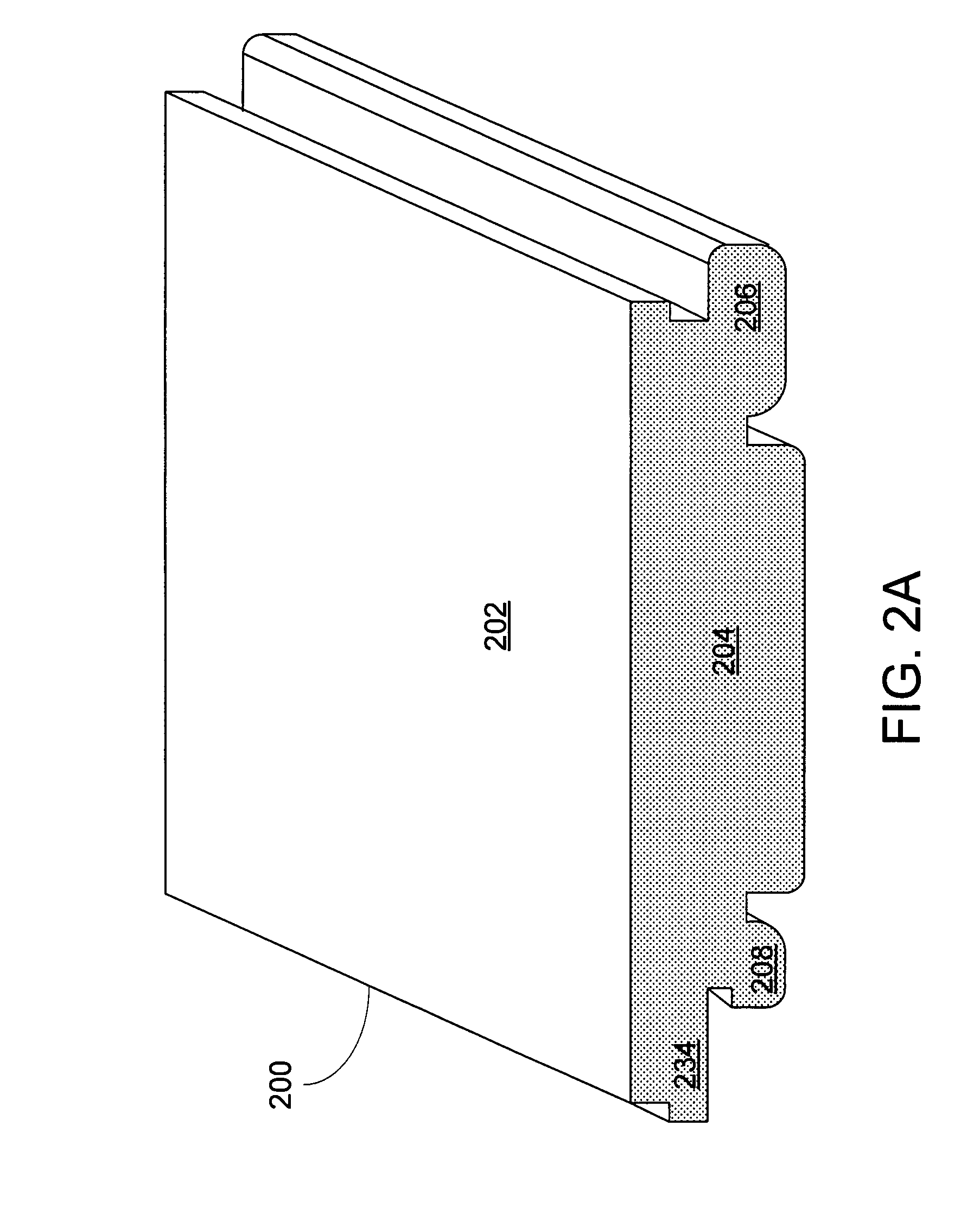
[0022]The present invention provides a locking system for floor boards. Floor board may be made from solid wood or composite wooden material with several layers or other suitable material. Each floor board has a profile with specially designed features that allow one floor board be easily joined with an adjacent floor board. The joined floor boards are further locked together with locking devices strategically distributed along the seam of two joined floor boards. FIG. 1A illustrates one embodiment of a locking device 100 and FIG. 1B illustrates a profile of the locking device 100. The locking device 100 is preferably made from a resilient and flexible material, such as steel, aluminum, plastic, rubber, etc. The locking device 100 has a base 102 with a first end 104 and a second end 106. A first protruding gripping extension 122 is located at the first end 104 and a second protruding gripping extension 120 is located at the second end 106. The top of the first protruding gripping ex...


PUM


Abstract

A locking system for floor boards comprises a plurality of floor boards and a plurality of locking devices. Each floor board has two tongues on one lateral side and another tongue and a locking groove on the opposite lateral side. The floor board also has two grooves on its bottom side. The locking device has three protruding gripping extensions. Few locking devices are placed on each floor board before the floor boards are sent to a job site. At the job site, two adjacent floor boards are assembled together by inserting the tongue of one board into a space defined by the locking device and the tongues of the adjacent board. The tongues are further secured in place by compression of flexible buffers located at each protruding gripping extension.

Description

FIELD OF THE INVENTION[0001]The invention relates to wood flooring, and more particularly, to a locking mechanism for flooring boards.BACKGROUND OF THE INVENTION[0002]Different systems have been used to ease construction of wood flooring; however, most of them present some deficiency especially in relation to engaging thin laminate “floating floor” surfaces. Traditional wood floors, which are joined by means of glued tongue-and-groove joints, wood floor panels have recently been developed which do not require the use of glue and instead are joined mechanically by means of so-called mechanical joint systems. These systems contain locking means which lock the panels horizontally and vertically. Typically, manufacturers of laminate flooring panels have produced flooring products that contain both a tongue and a groove profile within the same flooring panel. The tongue profile is machined into one side and one end of the panel with the groove being machined into the opposite side and en...

Claims


Application Information

Patent Timeline
IPC IPC(8): E04F15/02E04B5/00
CPCE04F15/04E04F2201/0517E04F2201/0153
Inventor LIU, DAVID C.
Owner LIU DAVID C
Features
  • Generate Ideas
  • Intellectual Property
  • Life Sciences
  • Materials
  • Tech Scout
  • Unparalleled Data Quality
  • Higher Quality Content
  • 60% Fewer Hallucinations
Learn More