
Ladder tray locking mechanism

a locking mechanism and ladder tray technology, applied in the field of ladders, can solve the problems of occupying additional space, difficult to attach or remove the tray from using a removable tool or paint tray with the ladder or step stool, so as to eliminate the need for hinges and improve the alignment of the locking pins

Active Publication Date: 2020-06-18
TRICAM IND
View PDF38 Cites 3 Cited by
  • Summary
  • Abstract
  • Description
  • Claims
  • Application Information

AI Technical Summary

Benefits of technology

The present invention is an improvement to a locking mechanism for a ladder tray. It provides more secure and rigid locking of the tray when in use. The locking mechanism allows for single-handed operation and eliminates the need for hinges. Springs are used to bias the locking pins and the tray's stored position is below the ladder handle. These changes result in a more efficient and durable locking mechanism for ladder trays.

Problems solved by technology

It is often inconvenient, however, to use a removable tool or paint tray with a ladder or step stool.
In some instances, the tray may be difficult to attach or remove from the ladder or step stool depending on the configuration of the top cap of the ladder or step stool.
The removable tray and ladder or step stool usually must be stored separately, taking up additional space.
Additionally, to move a ladder or step stool from place to place, the tray may need to be removed and carried separately because of weight or awkward transport configuration.
However, the use of links, such as in Astor, requires two hands to simultaneously release the tray lock mechanism.
Further, the use of links allows for potential pinching and takes up space beneath the tray.

Method used


Image

  • Ladder tray locking mechanism
  • Ladder tray locking mechanism
  • Ladder tray locking mechanism

Examples


Embodiment Construction

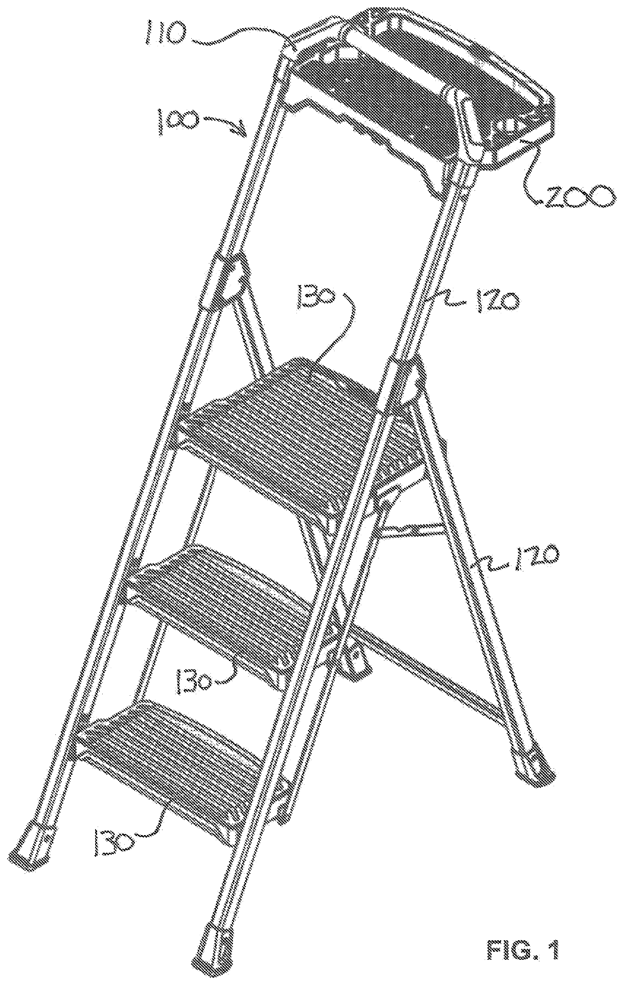
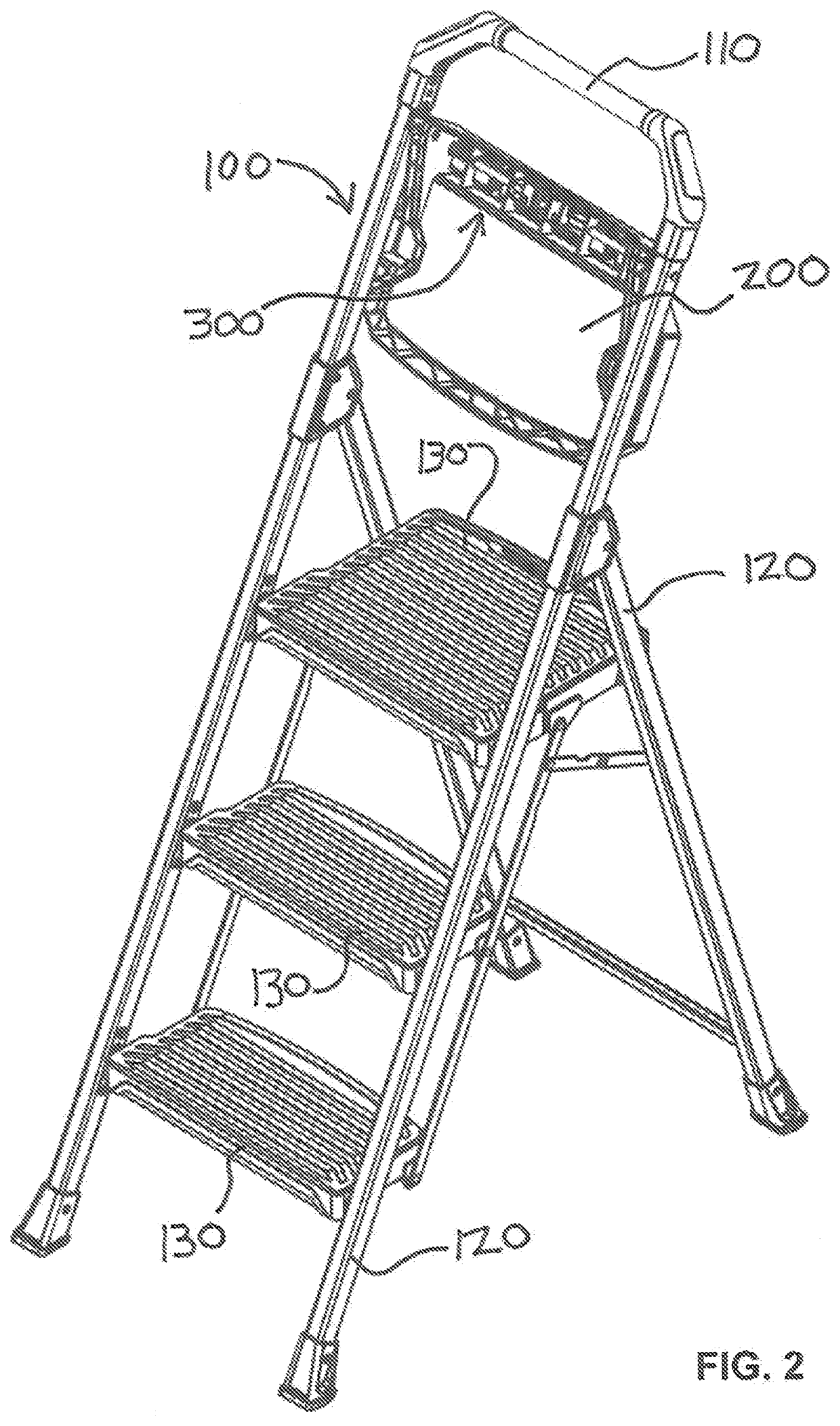
[0022]A stepladder according to an embodiment of the invention is depicted in FIGS. 1-9 by reference numeral 100. Stepladder 100 has a handle 110 that extends above a ladder tray 200 that may be used to hold tools and materials while using stepladder 100. It is understood that in place of handle 110, the frame of stepladder 100 may simply extend above the ladder tray 200 and act as handle 110. Stepladder includes rails 120 and steps 130. Ladder tray 200 is pivotable between an open position as shown in FIG. 1 and a stored position as shown in FIG. 2.

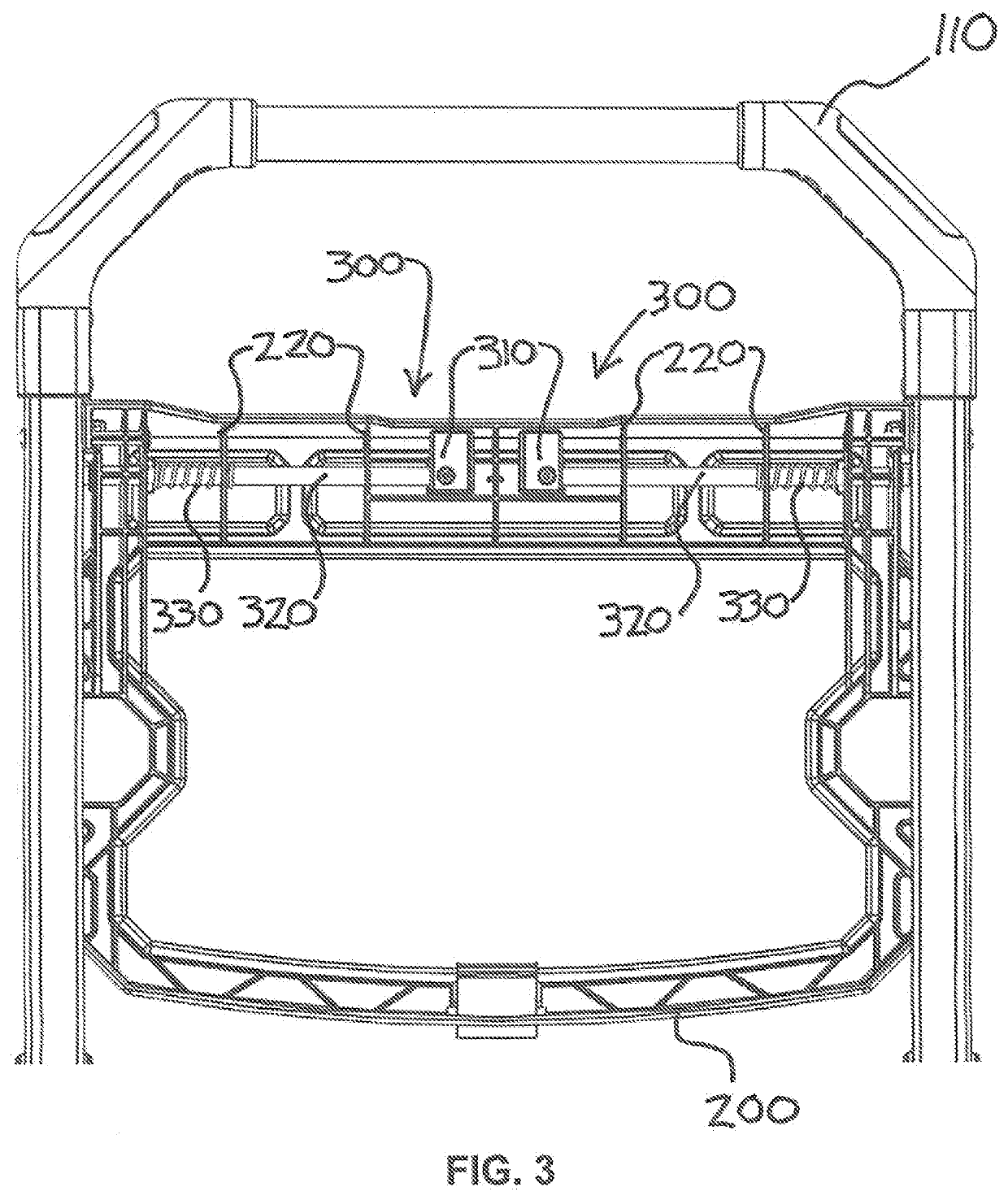
[0023]The stepladder 100 of the present invention utilizes a novel locking mechanism 300 to keep ladder tray 200 in the open position. Locking mechanism 300 preferably has two sliding rods 320 that are biased by springs 300 to a locked position as shown in FIG. 7. Other means of biasing the rods in the locked position known in the art may also be used. Rod ends 325 are configured to slide into and out of handle orifices 350 on the handle...


PUM


Abstract

A locking mechanism for a ladder tray is disclosed. The locking mechanism includes two locking points on the frame or handle of the ladder while allowing single-handed operation.

Description

CROSS-REFERENCE TO RELATED APPLICATION[0001]The present application claims the benefit of U.S. Provisional Application No. 62 / 779,633, filed Dec. 14, 2018, which is hereby incorporated herein in its entirety by reference.TECHNICAL FIELD[0002]The present disclosure relates generally to a ladder. More particularly, the present invention relates to a locking mechanism for a ladder tray that provides a more secure locking of the ladder tray when in the open position and a more rigid tray while also simplifying operation of the locking mechanism.BACKGROUND[0003]Ladders and step stools are generally known in the art. Because of their desired portability, foldable step ladders often include handles and other features that make them easier to transport. Lucci, U.S. Pat. No. 3,744,591, discloses a portable, folding step ladder.[0004]When working on a ladders or step stool, it is often desirable to have tools, paint, and other necessary objects within easy reach. For example, it is known to r...

Claims


Application Information

Patent Timeline
Patent Type & Authority Applications(United States)
IPC IPC(8): E06C7/14E06C7/16E06C7/48E05B15/02
CPCE06C7/14E05B15/0205E06C7/48E06C7/16E06C1/20E06C7/50E06C1/39
Inventor FOLEY, JOSEPH P.
Owner TRICAM IND
Learn More