Locking system for a footrest hanger

a locking system and footrest technology, applied in the field of wheelchairs, can solve the problems of cumbersome use, disengaging the hanger, and difficult use, and achieve the effect of improving the locking mechanism of the footrest, being secure and convenient to us

Inactive Publication Date: 2000-12-05
FREEDOM DESIGNS
View PDF11 Cites 8 Cited by
  • Summary
  • Abstract
  • Description
  • Claims
  • Application Information

AI Technical Summary

Benefits of technology

In light of the various problems with the prior art, the present invention seeks to provide an improved locking mechanism for a wheelchair footrest. The present invention provides a locking system that is secure and convenient to use. In general, this is accomplished with a biased system of mating surfaces on the side frame and the footrest hanger.

Problems solved by technology

A recurring problem with this arrangement is that when the user puts his or her foot down onto the footrest, the user's foot pushes the hanger downwardly, thereby disengaging the hanger from the engagement with the engagement pin.
A problem with this approach is that it is cumbersome for the user and is hard to use.

Method used


Image

  • Locking system for a footrest hanger
  • Locking system for a footrest hanger
  • Locking system for a footrest hanger

Examples


Embodiment Construction

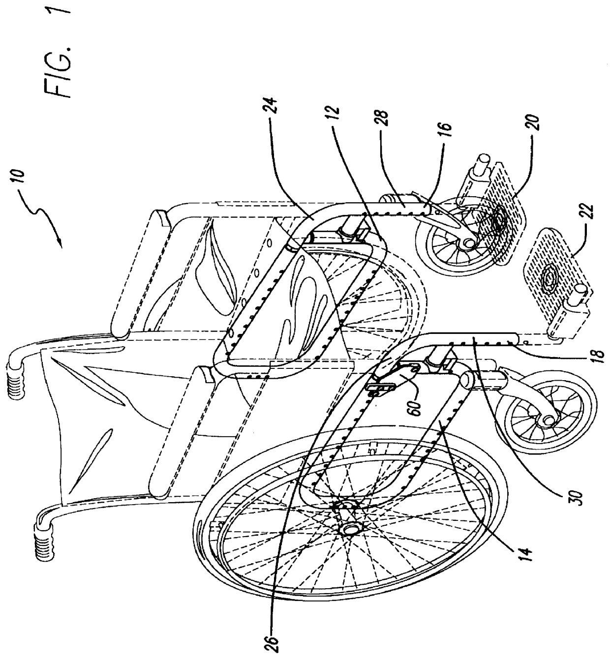
FIG. 1 illustrates a wheelchair 10 having right and left side frames 12 and 14. Right and left swing away footrest hangers 16 and 18 are locked on the right and left side frames 12 and 14, respectively. Right and left foot plates 20 and 22 are connected to the respective right and left footrest hangers 16 and 18, respectively. In this particular embodiment, the swing away footrest hangers 16 and 18 have respective upper portions 24 and 26 and respective lower portions 28 and 30. In this particular embodiment, the angle between the upper and lower portions of each swing away footrest is approximately 90 degrees. In other embodiments, the angle between the upper and lower portions of the footrest may be greater, for instance, in order to slightly extend the leg when resting on a respective foot plate.

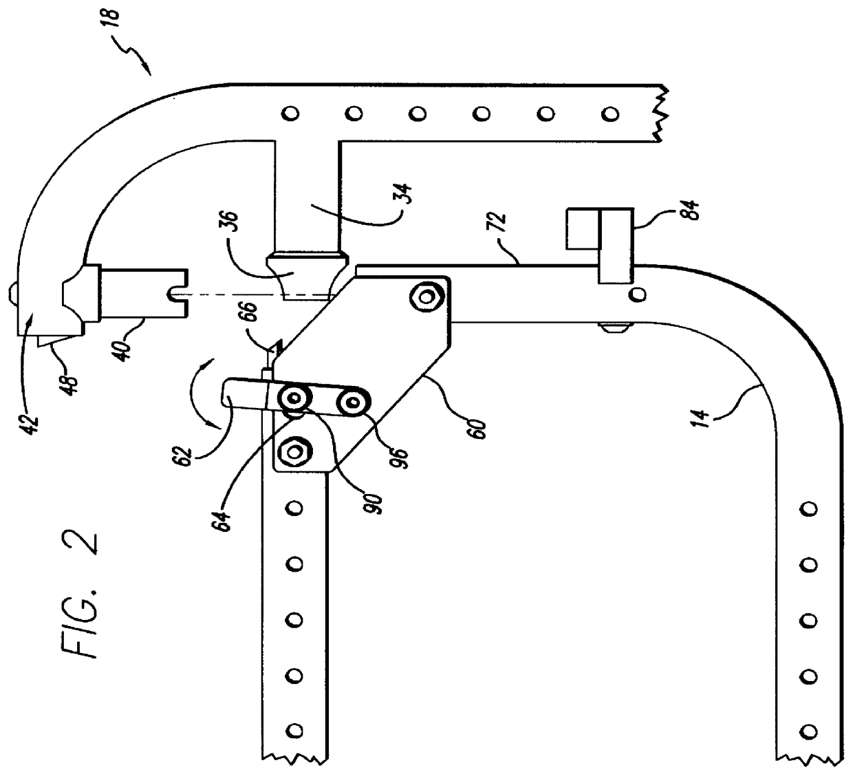
Considering the side frames and footrest hangers in more detail, FIG. 2 illustrates a side view of the left side frame 14 and the left swing away footrest hanger 18. In this particular dr...


PUM


Abstract

A locking system has a side frame having an open end and a spring-loaded hanger release insert extending therefrom. The system also has a hanger body having an upper portion with a terminal end. A hanger pivot fitting extends generally downwardly from the upper portion of the terminal end. A hanger locking surface extends outwardly from the terminal end. The spring-loaded hanger release insert has an upturned mating surface and the hanger locking surface has a downturned mating surface compatible with the upturned mating surface. A hanger release arm is interconnected with the spring-loaded hanger release insert. The system may further include a hanger brace extending from the hanger body, having an alignment guide at an end of the hanger brace. The hanger locking surface may have an angled, generally outwardly-extending face with a step, and the hanger release insert may have an angled, generally outwardly-extending face with a step, each of the steps defining a mutually-compatible mating surface. The side frame may further include a hanger support block extending from the side frame and adapted to support the hanger brace when the hanger brace is locked onto the side frame. The side frame may comprise a top, a bottom, a first side and a second side. The side frame may further comprise a hanger plate extending between the top and the first side. The hanger release arm is then connected to the hanger plate. The side frame comprises a tube, and a portion of the hanger release insert is secured within the tube. A compression spring or other biasing mechanism is secured within the tube to provide compression force against the hanger release insert. The locking surface may be a portion of a side frame locking piece, the hanger comprising a tube. A portion of the locking piece may be secured within the tube, the locking surface extending out of the tube.

Description

I. BACKGROUND OF THE INVENTIONa. Field of the InventionThe present invention relates to wheelchairs and, in particular, to a locking mechanism to lock a footrest hanger onto a wheelchair side frame.b. Prior ArtThe typical wheelchair is provided with footrest hangers that extend downwardly in front of the wheelchair from respective wheelchair side frames for the purpose of supporting the footrests. When the user sits in the wheelchair, a footrest provides support for the user's feet. The typical footrest hanger has an upper portion that extends out of the wheelchair side frame and which then curves into a substantially straight downwardly-extending portion that leads to the footrest. The hanger is typically removably locked onto the side frame, but the lock is releasable so that the hanger can be taken off.Prior art approaches to locking the hanger into position on the wheelchair have drawbacks. One approach is to mount a spring loaded pin in the interior of a portion of the side fra...

Claims


Application Information

Patent Timeline
Patent Type & Authority Patents(United States)
IPC IPC(8): A61G5/00A61G5/12
CPCA61G5/12A61G2005/128A61G2005/1054A61G5/1054A61G5/128
Inventor MELGAREJO, MAURICIOMELGAREJO, ALEJANDRO
Owner FREEDOM DESIGNS
Why Eureka
Try Eureka