

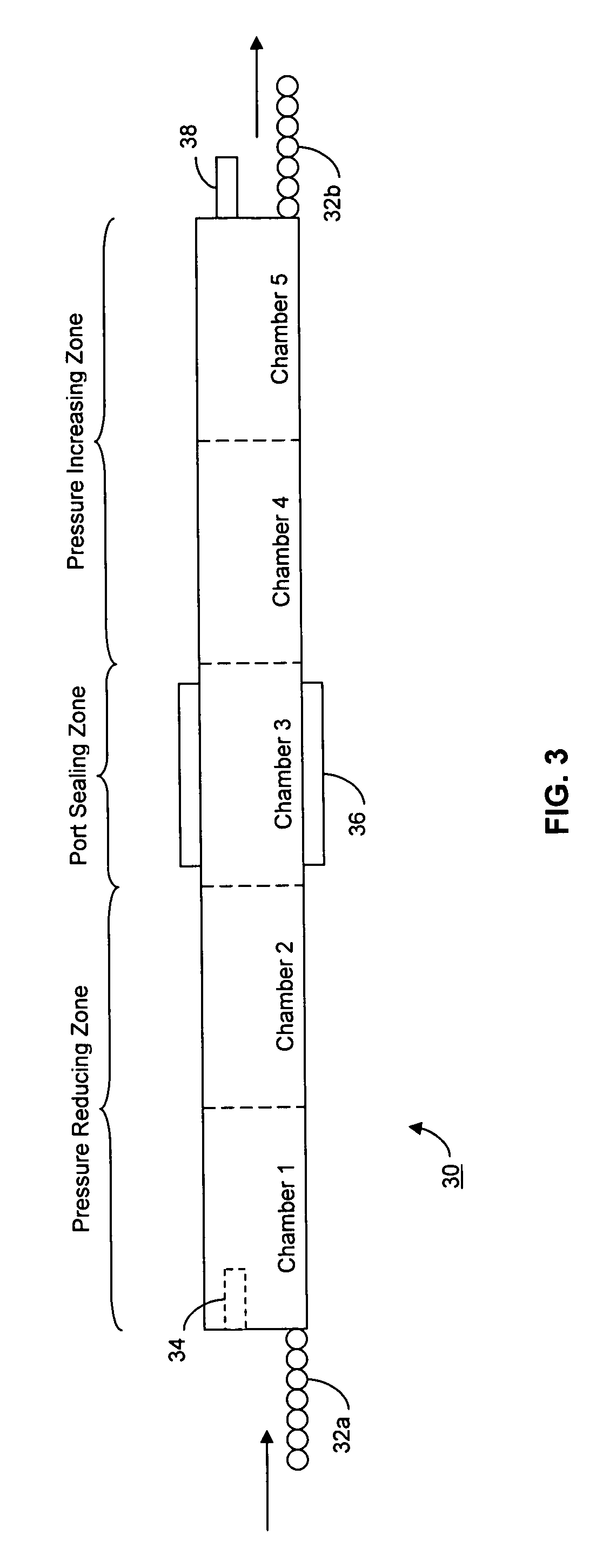
Evacuation and port sealing techniques for vacuum insulating glass units, and/or vacuum oven for accomplishing the same
a technology of vacuum insulating glass and sealing techniques, which is applied in the direction of doors/windows, layered products, chemistry apparatuses and processes, etc., can solve the problems of inconvenient operation, complicated machinery design, and inability to meet the needs of vig production systems,
- Summary
- Abstract
- Description
- Claims
- Application Information
AI Technical Summary
Benefits of technology
Problems solved by technology
Method used
Image

Examples
Embodiment Construction
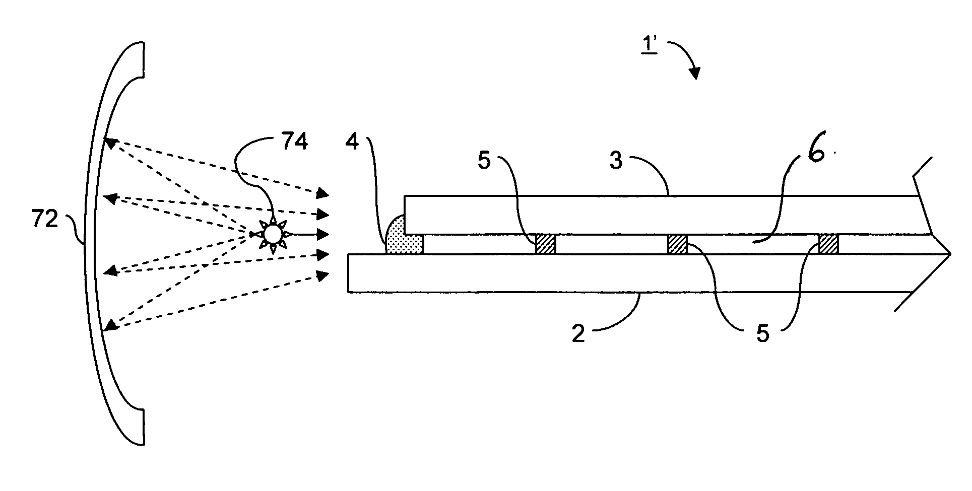
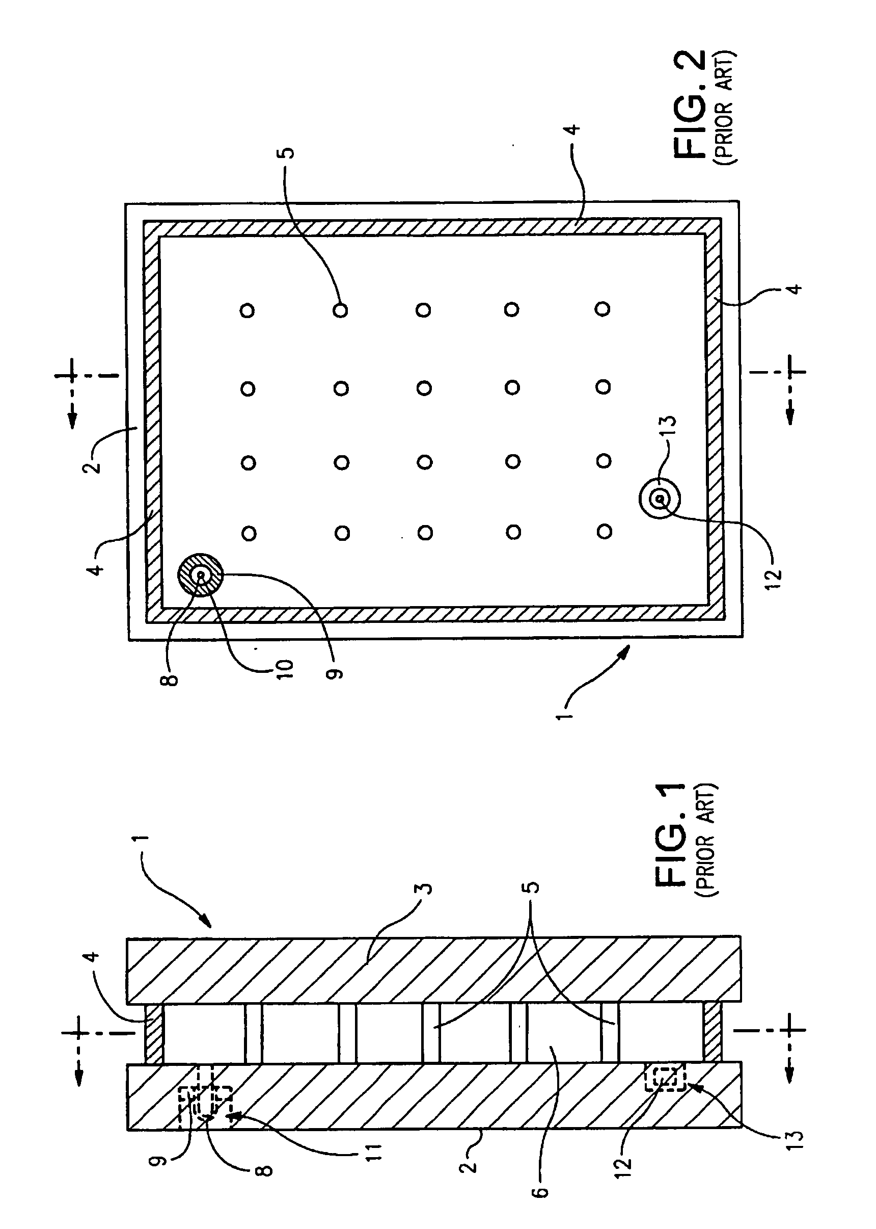
[0025]Certain embodiments of this invention relate to an improved peripheral or edge seal in a vacuum IG window unit, and / or a method of making the same. “Peripheral” and “edge” seals herein do not mean that the seals are located at the absolute periphery or edge of the unit, but instead mean that the seal is at least partially located at or near (e.g., within about two inches) an edge of at least one substrate of the unit. Likewise, “edge” as used herein is not limited to the absolute edge of a glass substrate but also may include an area at or near (e.g., within about two inches) of an absolute edge of the substrate(s). Also, it will be appreciated that as used herein the term “VIG assembly” refers to an intermediate product prior to at least the evacuation of the gap including, for example, two parallel-spaced apart substrates and a frit. Also, while the frit may be said to be “on” or “supported” by one or more of the substrates herein, this does not mean that the frit must direc...
PUM
| Property | Measurement | Unit |
|---|---|---|
| temperature | aaaaa | aaaaa |
| temperature | aaaaa | aaaaa |
| reduced pressure | aaaaa | aaaaa |
Abstract
Description
Claims
Application Information