LED illuminated tool

Inactive Publication Date: 2009-06-18
NEVIN DONALD
View PDF6 Cites 2 Cited by
  • Summary
  • Abstract
  • Description
  • Claims
  • Application Information

AI Technical Summary

Benefits of technology

[0029]In general, those objects are achieved by the present invention which relates to a tool with a handle and a rigid shaft having an end. The shaft extends from the handle and has an internal bore. The bore extends through the shaft from the handle to the end of the shaft

Problems solved by technology

However, such light sources must be held by the user while using the screwdriver, forcing the user to manipulate the screwdriver and the screw with one hand, while holding the light source with the other.
Manipulating the screwdriver and the screw with one hand is difficult.
However, the devices disclosed in the above mentioned patents have a disadvantage inherent in having such a bulb located in the handle, and thus far from the screw-engaging end of the shaft, which is the point where illumination is required.
Because the light from the bulb spreads out as it travels along the shaft, and because of the limitations on the light output of a standard battery operated incandescent bulb, placing the bulb in the handle has proven to be less than adequate for illuminating the area immediately in

Method used


Image

  • LED illuminated tool
  • LED illuminated tool
  • LED illuminated tool

Examples


Example

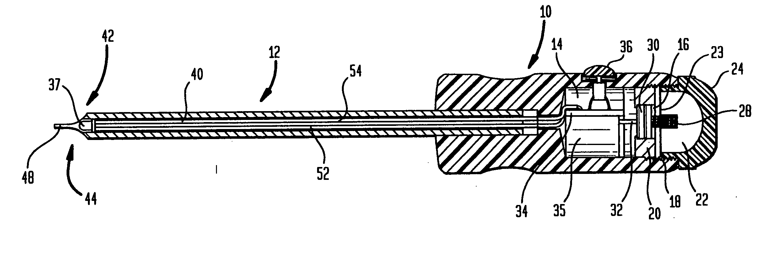
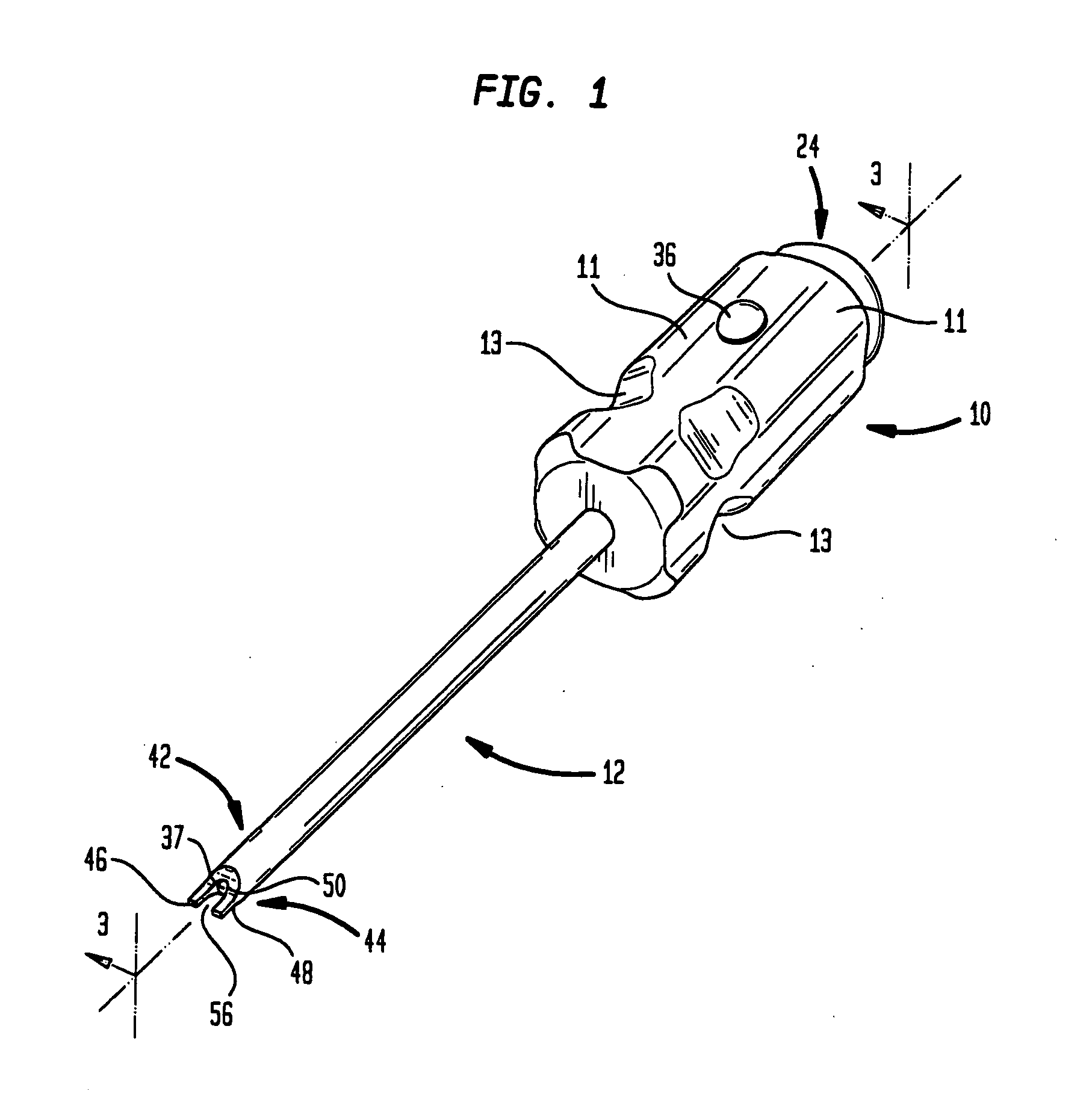
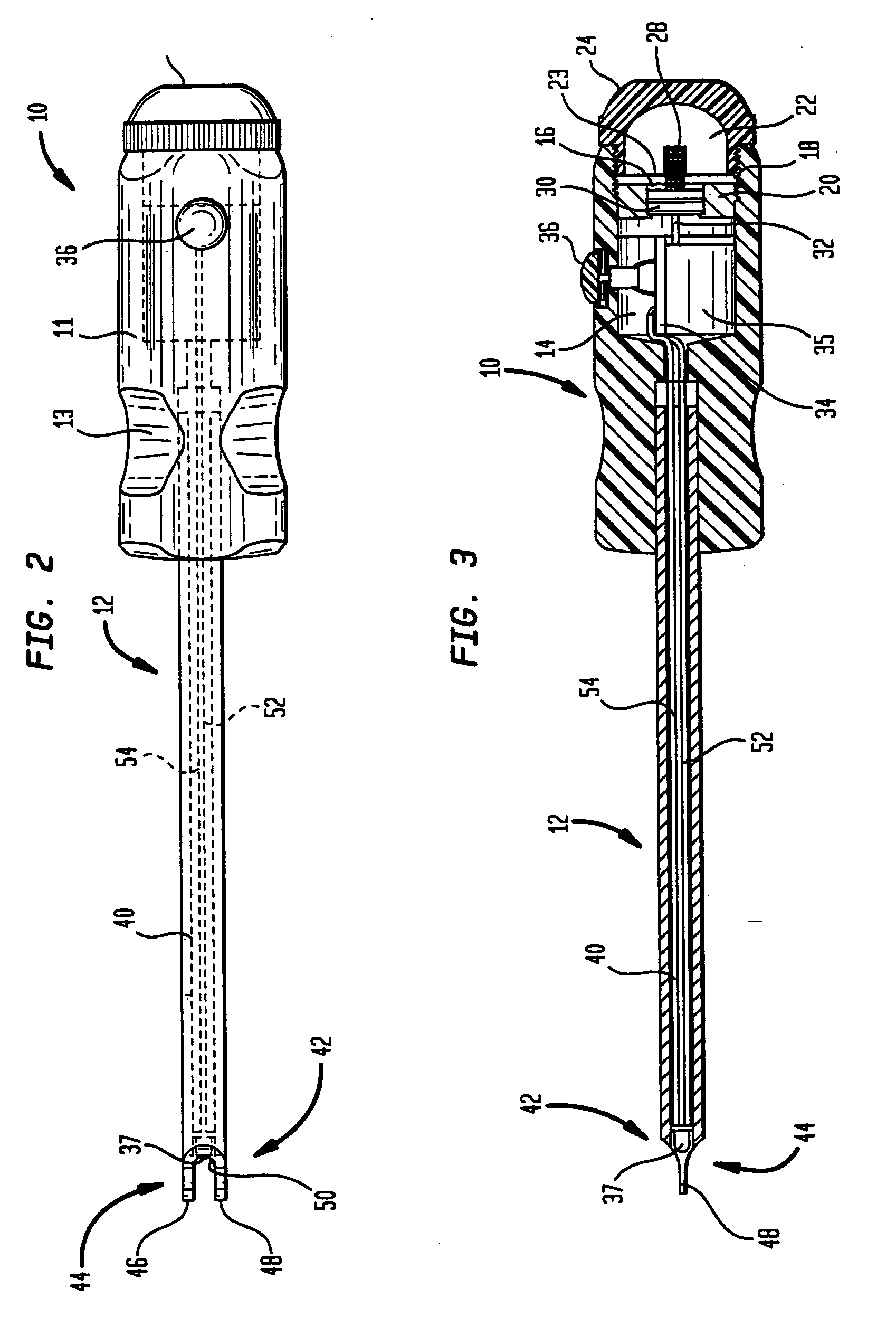
[0046]As seen in FIGS. 1-3, the first preferred embodiment of the tool of the present invention takes the form of a screwdriver which includes a handle, generally designated 10, from one end of which a shaft, generally designated 12, extends. Handle 10 is preferably provided with circumferentially spaced outwardly protruding grip members 11 with recesses 13 to accommodate the fingers of the user. Shaft 12 is preferably made of hardened steel and preferably has a diameter of approximately one quarter of an inch.

[0047]Handle 10 may be made of any conventional material, such as plastic, rubber or wood. Handle 10 has a hollow cavity 14. Within cavity 14 is situated an open ended battery receiving chamber 16. Chamber 16 is defined by a substantially cylindrical wall formed of an electrically conductive outer wall layer 18 and an electrically non-conductive inner wall layer 20.

[0048]The rear end of cavity 14 defines an internally threaded battery receiving opening 22. Opening 22 is adapte...


PUM


Abstract

The tool has a handle and a rigid shaft that extends from the handle. The shaft has an end. It also has a bore that extends from the handle to the end of the shaft. A LED is situated in the bore, proximate the end of the shaft. The handle has a recess. A battery is situated within the recess. The LED is electrically connected to battery by a wire extending through the bore, between the LED and the handle. In the screwdriver embodiments, the end of the shaft is designed to engage a screw. Interchangeable heads are provided in the screwdriver embodiment for use with screws of various configurations. In another embodiment, the end of the shaft is planar such that light from the bore can illuminate hard to reach areas or focus on a small area.

Description

CROSS-REFERENCE TO RELATED APPLICATIONS[0001]Priority is claimed on Provisional Patent Application Ser. No. 60 / 936,269, filed Jun. 19, 2007. Further, this is a Continuation-In-Part of copending application Ser. No. 12 / 006,516, filed Jan. 3, 2008, entitled: “Led Illuminated Screwdriver”.STATEMENT REGARDING FEDERALLY SPONSORED RESEARCH OR DEVELOPMENT[0002]Not ApplicableREFERENCE TO A “SEQUENCE LISTING”, A TABLE, OR A COMPUTER PROGRAM LISTING APPENDIX SUBMITTED ON COMPACT DISC[0003]Not ApplicableBACKGROUND OF THE INVENTION[0004]1. Field of the Invention[0005]The present invention relates to tools for driving fasteners such as screws or for illuminating hard to reach areas, and more particularly, to an illuminating tool having an LED situated in a bore extending through the shaft.[0006]2. Description Of Prior Art Including Information Disclosed Under 37 CFR 1.97 and 1.98[0007]Tools for driving fasteners such as screws are common. Conventional tools of this type include a solid handle, m...

Claims


Application Information

Patent Timeline
IPC IPC(8): B25B23/18
CPCB25B23/18B25B15/02
Inventor NEVIN, DONALD
Owner NEVIN DONALD
Why Eureka
Try Eureka