
Machine tool system

a machine tool and terminal technology, applied in the direction of computer control, program control, instruments, etc., can solve the problems of large-size information transmission and reception difficulties, and achieve the effect of saving time and effort, quick and reliable transmission of information, and expanding the movement range of the operator carrying the terminal body

Active Publication Date: 2019-01-08
MURATA MASCH LTD
View PDF11 Cites 0 Cited by
  • Summary
  • Abstract
  • Description
  • Claims
  • Application Information

AI Technical Summary

Benefits of technology

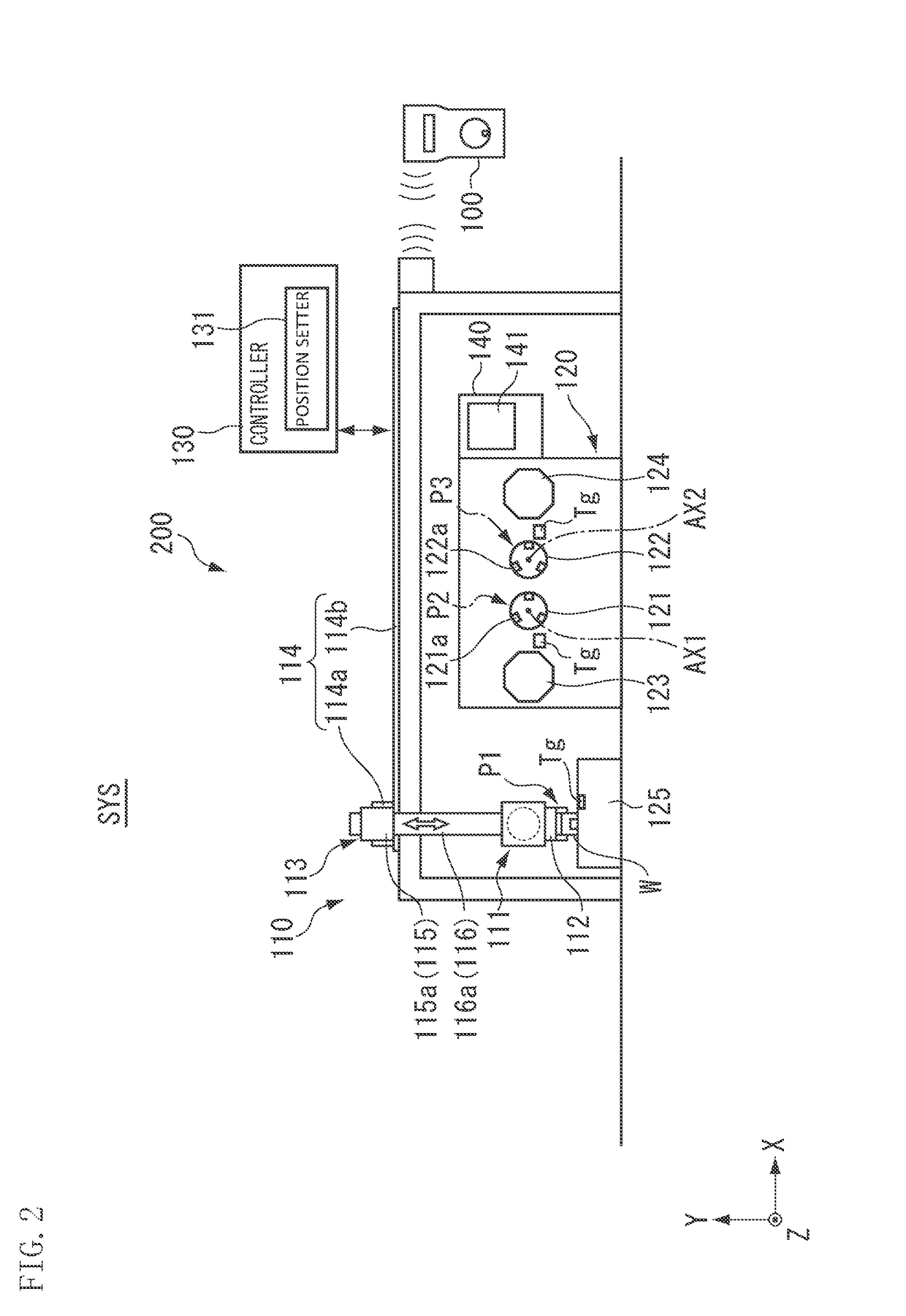
The present invention is about a machine tool system that uses a wireless communication system between a terminal body and an industrial machine. This system allows the terminal body to transmit and receive large-size data, such as image information, quickly and reliably. The terminal body is wireless or cordless, which expands the movement range of the operator and allows for easy acquisition of information. The terminal body also has a display for checking and transmitting images, as well as an illuminator for assisting in dark areas. The machine tool system detects the position of an identifier on the terminal body and uses it to set the stop or passage position of a workpiece support on the machine tool system, making the process easier and more efficient. Overall, the invention improves the speed and accuracy of information transmission and catering to the needs of the operator.

Problems solved by technology

However, Japanese Unexamined Patent Application Publication No. 2013-222381 does not conceive of the communication of information different from operation information between the operation terminal and the industrial machine and therefore has difficulty in transmitting and receiving, for example, large-size information.

Method used


Image

  • Machine tool system
  • Machine tool system
  • Machine tool system

Examples


Embodiment Construction

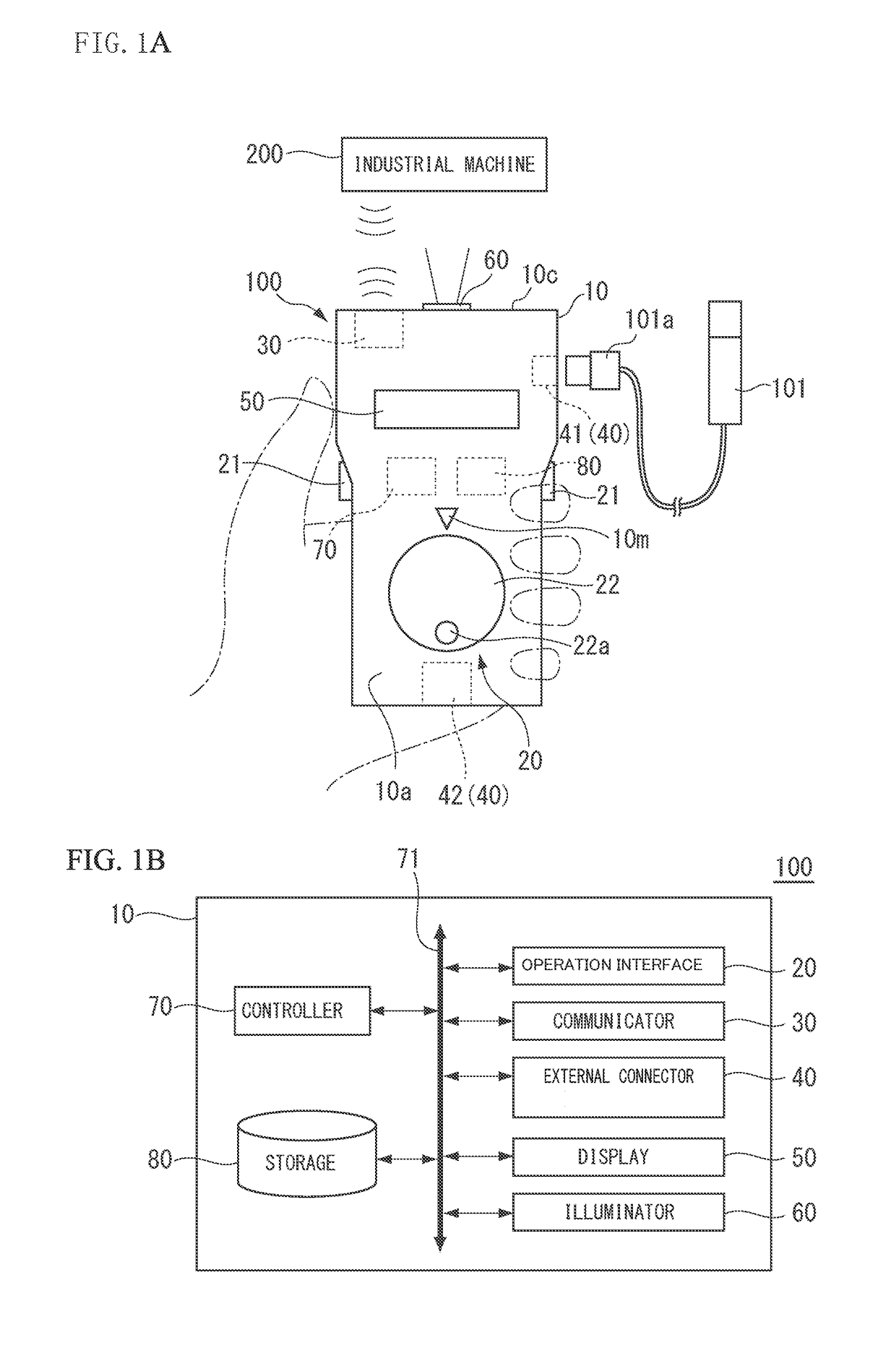
[0020]Now, preferred embodiments of the present invention will be described with reference to the drawings. However, the present invention is not limited thereto. To clarify the preferred embodiments, the drawings are scaled, for example, partially enlarged or highlighted, as necessary. The present preferred embodiment provides a method for operating an industrial machine using a portable operation terminal by wireless communication. The method includes inputting image information about an image to the operation terminal or detecting information about an identifier disposed in a predetermined position using the operation terminal and transmitting the inputted image information or the detected information about the identifier from the operation terminal.

[0021]FIG. 1A is a diagram showing an example of an operation terminal 100 of the present preferred embodiment. FIG. 1B is a block diagram showing an example of the operation terminal 100.

[0022]The operation terminal 100 is a portable...


PUM


Abstract

A machine tool system includes a portable operation terminal capable of operating an industrial machine by wireless communication and including a terminal body including an external connector that is able to receive image information about an image and a communicator that is able to transmit the image information received by the external connector.

Description

BACKGROUND OF THE INVENTION[0001]1. Field of the Invention[0002]The present invention relates to an operation terminal, a machine tool system, and a method for operating an industrial machine.[0003]2. Description of the Related Art[0004]There are industrial machines including a loader that carries a workpiece, a machine tool that machines the workpiece, and a controller that controls the loader and a machining device. Such an industrial machine is typically operated under the automatic control of the controller, but it may be manually operated, for example, when teaching or the like is performed on the loader. There is known an operation terminal that when manually operating a loader, the operator is able to carry so that the operator is able to check the operating area of the loader nearby (for example, see Japanese Unexamined Patent Application Publication No. 2013-222381). According to Japanese Unexamined Patent Application Publication No. 2013-222381, the operation terminal and ...

Claims


Application Information

Patent Timeline
Patent Type & Authority Patents(United States)
IPC IPC(8): G05B19/404H04Q9/00G05B19/409G08C17/02
CPCG05B19/404G05B19/409G08C17/02H04Q9/00G08C2201/30G05B2219/36159G05B2219/37582B23Q7/04
Inventor KAWAI, HIDETSUGU
Owner MURATA MASCH LTD
Learn More