Arm prosthetic device

a prosthetic device and arm technology, applied in the field of prosthetics, can solve the problems of limited options for patients, limited capabilities of prosthetics with respect to finer tasks, etc., and achieve the effects of improving tactile capabilities, improving user comfort, and improving range of motion

Active Publication Date: 2008-11-20
DEKA PROD LLP
View PDF98 Cites 60 Cited by
  • Summary
  • Abstract
  • Description
  • Claims
  • Application Information

AI Technical Summary

Benefits of technology

[0006]It is one aspect of the present device to provide a prosthetic that will allow the user improved range of motion, improved tactile capabilities, increased comfort for the user, and decreased reliance on manual positioning of the prosthesis.

Problems solved by technology

Further, there are limited options for those patients who have lost their entire arm, shoulder to hand.
These prosthetics give limited capability with respect to, amongst other things, finer tasks.

Method used


Image

  • Arm prosthetic device
  • Arm prosthetic device
  • Arm prosthetic device

Examples


Embodiment Construction

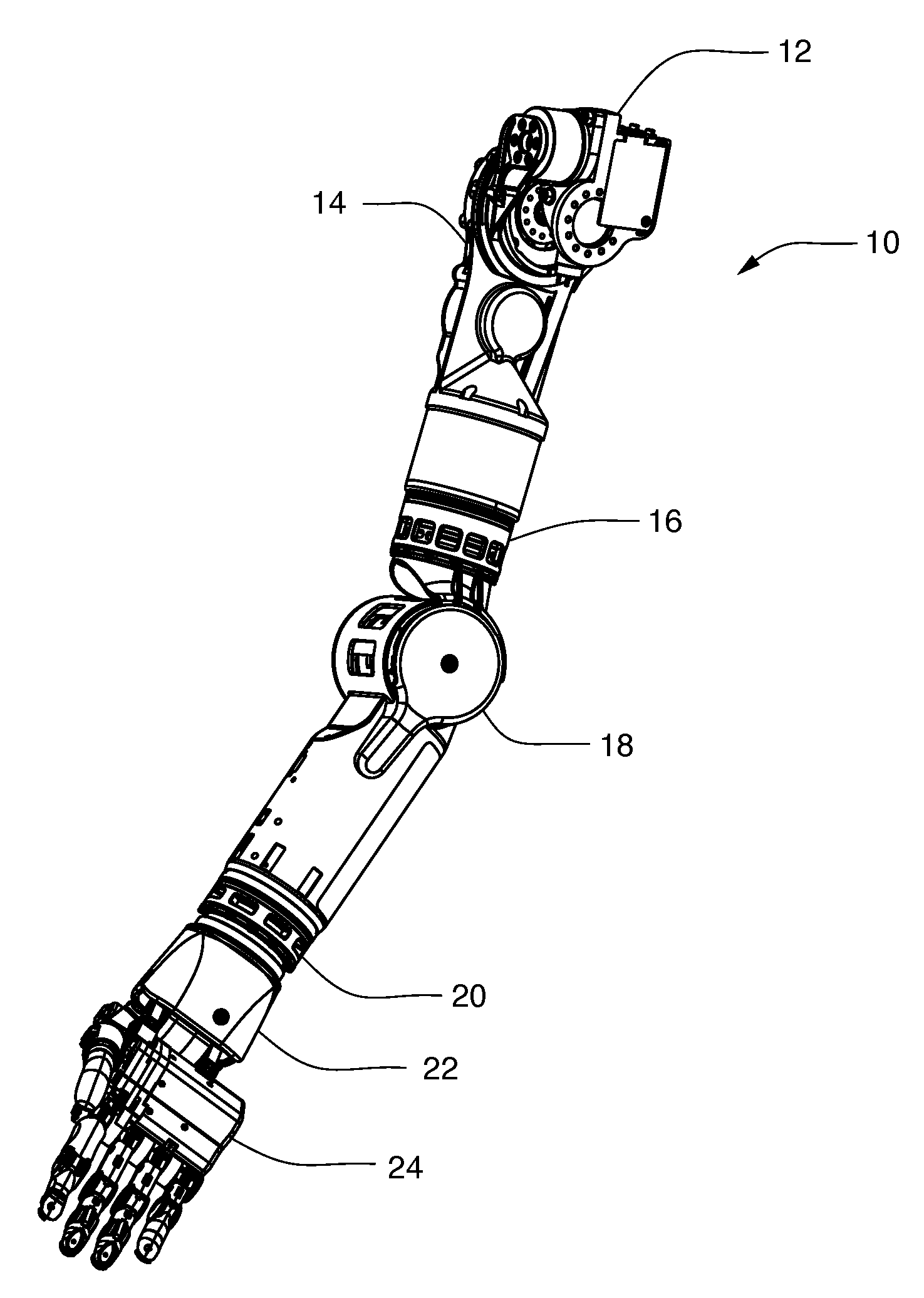
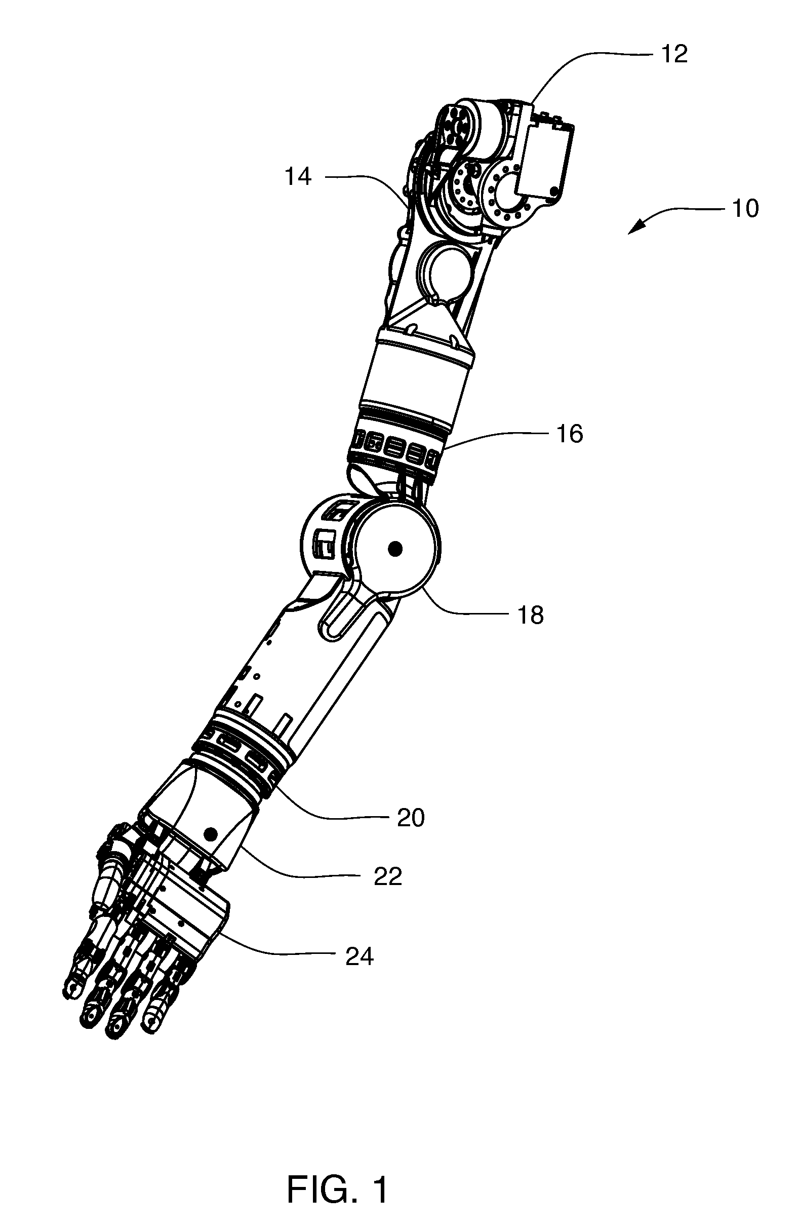
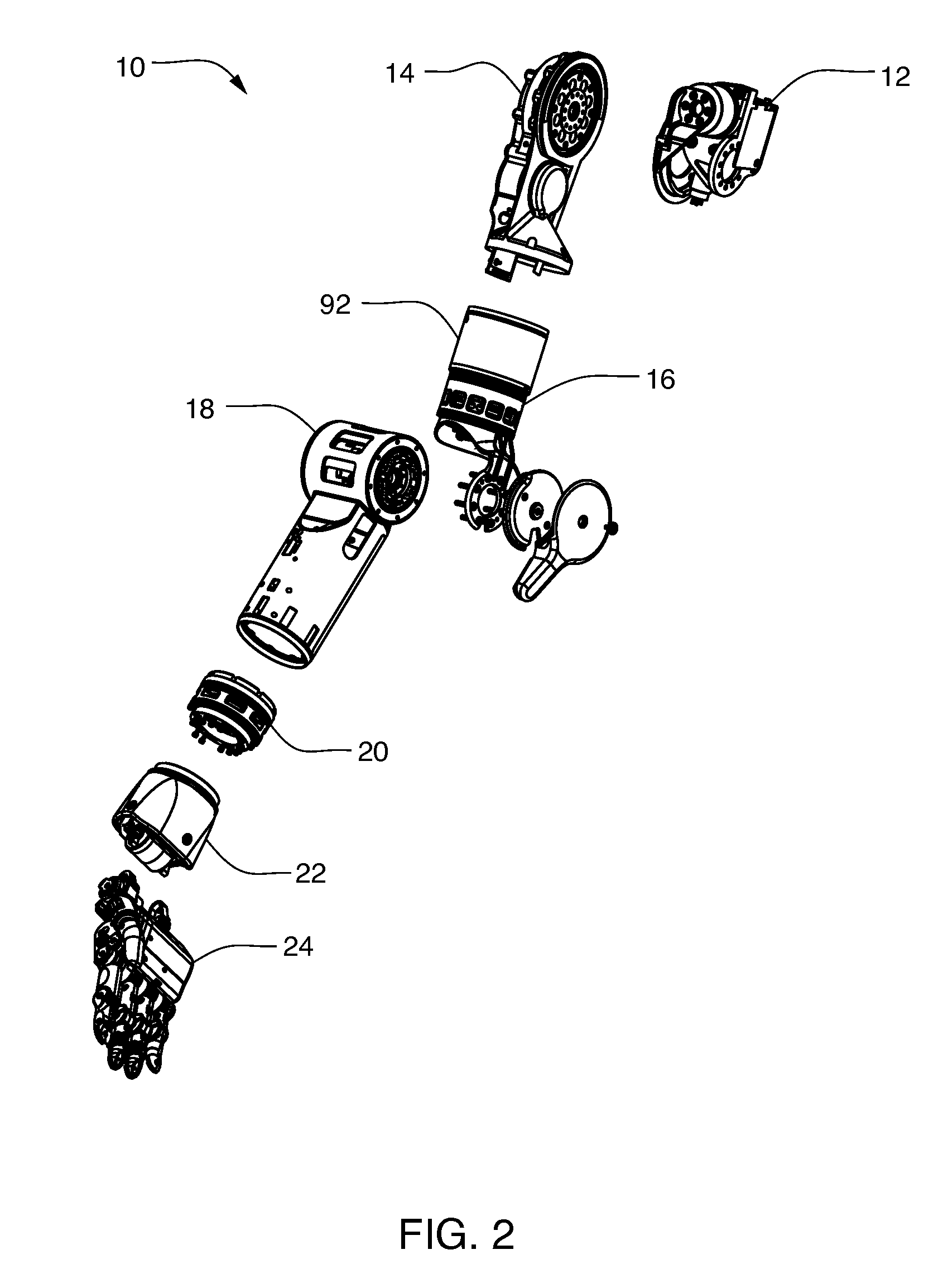
[0075]Referring to FIGS. 1 and 2, a prosthetic arm apparatus 10 for attachment to a shoulder of a shoulder disarticulated amputee includes a plurality of segments, including a shoulder abductor 12, a shoulder flexion assembly 14, a humeral rotator 16, an elbow flexion assembly 18, a wrist rotator 20, a wrist flexion assembly 22, and a hand assembly 24. The prosthetic arm apparatus 10, in the exemplary embodiment, has the dimensions and weight of a female arm of a fiftieth percentile, so that many different users may comfortably use the prosthetic arm apparatus 10. As should be understood by those skilled in the art, the prosthetic arm apparatus 10 may be constructed to larger or smaller dimensions if desired.

[0076]Referring to FIG. 3, one embodiment of the shoulder abductor 12 is shown. The shoulder abductor 12 includes a harness mount 26. The harness mount 26 has harness interface holes 28 that may be used to attach the abductor 12 to a prosthetic harness (not shown) or other syste...


PUM


Abstract

A prosthetic arm apparatus comprising a plurality of segments that provide a user of the prosthetic arm apparatus with substantially the same movement capability and function as a human arm.

Description

CROSS REFERENCE TO RELATED APPLICATIONS[0001]This application claims priority from and incorporates by reference in its entirety U.S. Provisional Patent Application Ser. No. 60 / 899,833, filed Feb. 6, 2007, entitled “Arm Prosthetic Device” and U.S. Provisional Patent Application Ser. No. 60 / 963,639, filed Aug. 6, 2007, entitled “Arm Prosthetic Device.”STATEMENT OF GOVERNMENT INTEREST[0002]This invention was made with Government support under Contract Number W911NF-06-C-001 awarded by the U.S. Army RDECOM ACQ CTR. The Government has certain rights in the invention.TECHNICAL FIELD[0003]The present development relates to mechanical and medical devices and, more particularly, to prosthetics. More particularly, the development utilizes mechanical structure and user or motor stimuli to operate the prosthesis similarly to a human limb.BACKGROUND INFORMATION[0004]Existing prosthetic arms having limited movement for the user. Further, there are limited options for those patients who have lost...

Claims


Application Information

Patent Timeline
Patent Type & Authority Applications(United States)
IPC IPC(8): A61F2/66A61B5/103A61F2/48
CPCA61F2/54A61F2220/0075A61F2/582A61F2/585A61F2/586A61F2/68A61F2002/30464A61F2002/5061A61F2002/5083A61F2002/587A61F2002/6836A61F2002/6845A61F2002/701A61F2002/7625A61F2002/7635A61F2002/764A61F2002/7862A61F2/581A61F2/78A61F2002/30462A61F2/70A61F2002/543A61F2002/546A61F2002/5069A61F2002/507A61F2002/6827A61F2002/6854A61F2002/6863A61F2002/704A61F2002/5059A61F2002/5001A61F2/583
Inventor LANGENFELD, CHRISTOPHER C.EVANS, CHRISTOPHER O.SMITH, III, STANLEY B.MULLER, ALEXANDER H.KERWIN, JOHN M.SCHNELLINGER, THOMAS S.GUAY, G. MICHAELVAN DER MERWE, DIRK A.
Owner DEKA PROD LLP
Why Eureka
Try Eureka