Method and apparatus for improving the operation of a remote viewing device

a technology of remote viewing and operation method, which is applied in the field of system and method for can solve the problems of reducing the range of motion of the viewing head, imprecise operation, etc., and achieve the effect of improving the operation of the remote viewing devi

Active Publication Date: 2005-08-04
GE INSPECTION TECH LP
View PDF53 Cites 62 Cited by
  • Summary
  • Abstract
  • Description
  • Claims
  • Application Information

AI Technical Summary

Benefits of technology

[0006] In one aspect, the invention features a method for improving the operation of a remote viewing device. The method comprises removing at least a portion of slack from at least one control cable attached to a servo motor. The removal of the at least a portion of slack includes at least changing a distance between the servo motor and a flexible tube termination block until a specified tension is encountered in the at least one control cable. The method also comprises fixing the servo motor where the specified tension is encountered and determining a first servo control signal value corresponding to no angular deflection in a viewing head of the remote viewing device. In addition the method comprises increasing the viewing head's range of motion. The process of increasing the viewing head's range of motion includes at least determining a second servo control signal value corresponding to a first angular deflection in the viewing head.
[0008] In yet an additional embodiment, the method further comprises placing a first recalibration cap over the viewing head, wherein the first recalibration cap fixes the viewing head in a non-deflected position. In yet a further embodiment, the determining a second servo control signal value includes: placing a second recalibration cap over the viewing head, wherein the second recalibration cap allows the viewing head to deflect a first number of degrees; and rotating the viewing head the first number of degrees until it is in contact with the second recalibration cap. In still another embodiment, the first and second servo control signal values are used to recalibrate the operation of the remote viewing device to increase the viewing head's range of motion.
[0010] In another aspect, the invention features a system for improving the operation of a remote viewing device. The method comprises a remote viewing device control unit; a remote viewing device viewing head; a remote viewing device flexible tube connected at a proximal end to the control unit and at the distal end to the viewing head; and at least one servo motor located in the control unit and connected to at least one control cable that passes through the flexible tube and is attached to the viewing head, a distance between the at least one servo motor and a flexible tube termination block capable of being varied to remove at least a portion of slack in the at least one control cable.
[0016] In a further aspect, the invention features a system for improving the operation of a remote viewing device. The system comprises a remote viewing device control unit including at least a microprocessor, a memory unit, a servo control unit, and a servo motor, the microprocessor operatively coupled to the memory unit and the servo control unit and the servo motor operatively coupled to the servo motor control unit; a remote viewing device viewing head; a remote viewing device flexible tube connected at a proximal end to the control unit and at the distal end to the viewing head; at least one control cable connected to the servo motor and the remote viewing device viewing head and passing through the remote viewing device flexible tube; and a software routine stored in the memory unit, the software routine directing the microprocessor and the servo control unit to extend a range of motion of the viewing head. In one embodiment, the extending the range of motion of the viewing head includes at least determining servo control signal values corresponding to a deflected and a non-deflected location of the viewing head.

Problems solved by technology

Over the life of a remote viewing device, numerous factors including cable stretch and increased friction and stiffness can lead to imprecise operation and a decrease in the viewing head's range of motion.

Method used


Image

  • Method and apparatus for improving the operation of a remote viewing device
  • Method and apparatus for improving the operation of a remote viewing device
  • Method and apparatus for improving the operation of a remote viewing device

Examples


Embodiment Construction

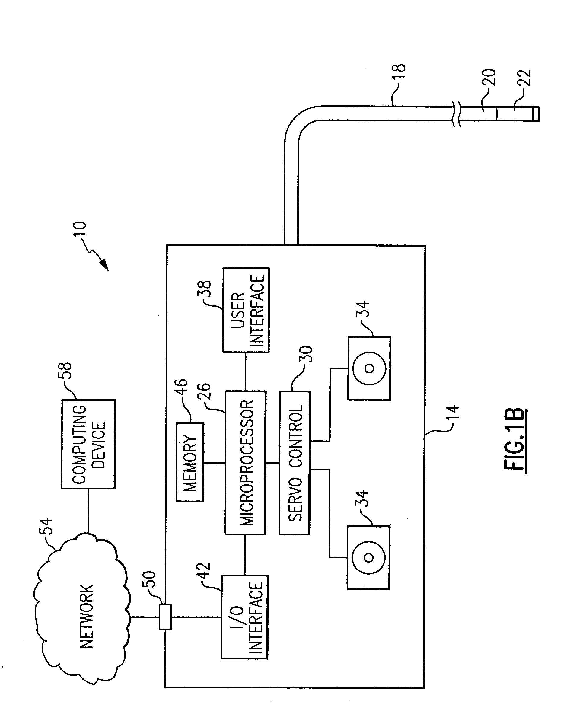
[0025] The present invention features a remote viewing device (a remote viewing device refers generally to borescopes, fiberscopes, endoscopes, and the like) that is capable of improving its operation by removing slack in its control cables and / or increasing the range of motion of its viewing head. The procedure for improving the operation involves recalibrating the control cable servo motors and can involve changing the stroke of and / or the force applied by the servo motors. The procedure is significantly automated and can be performed without the need for a specialized recalibration technician.

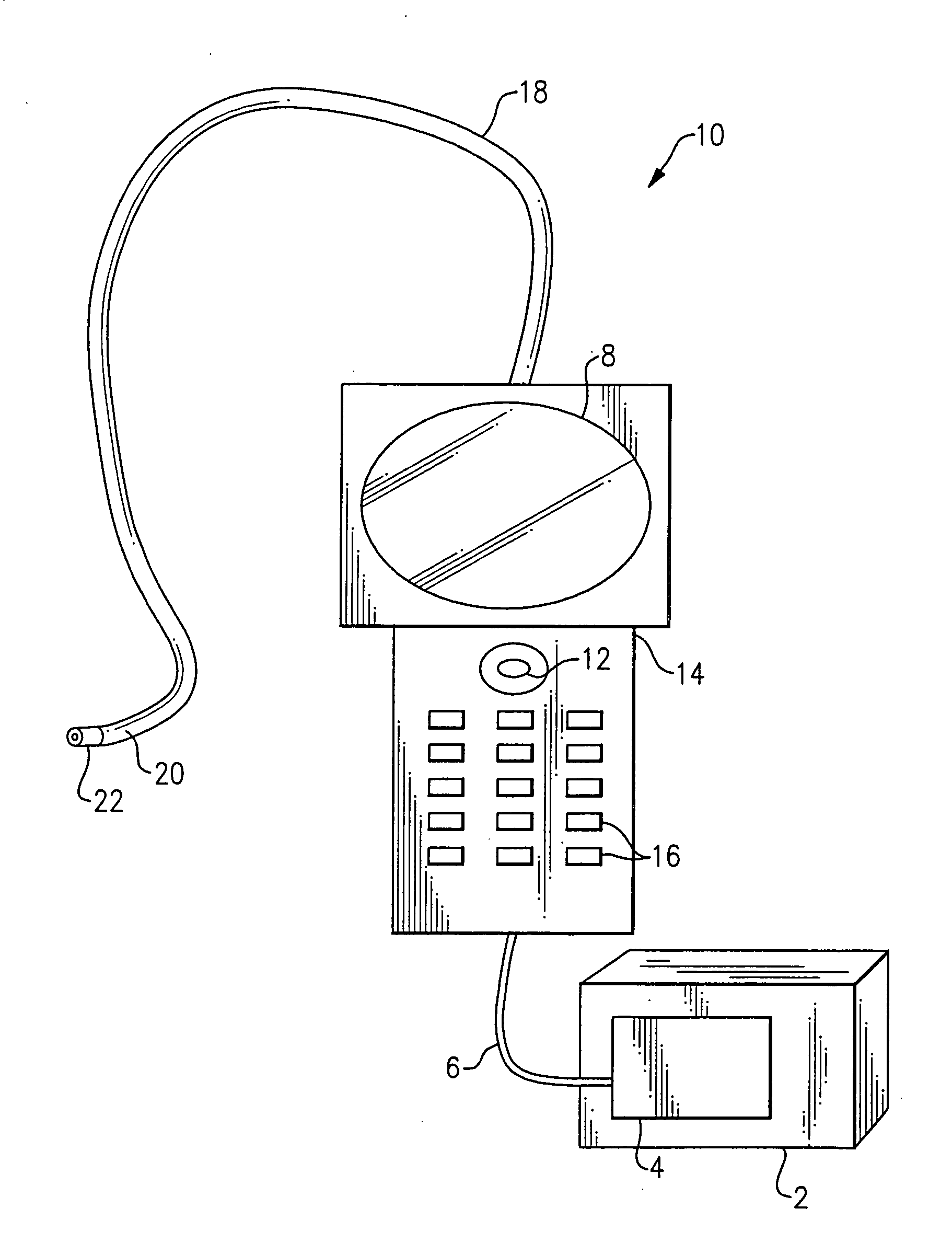
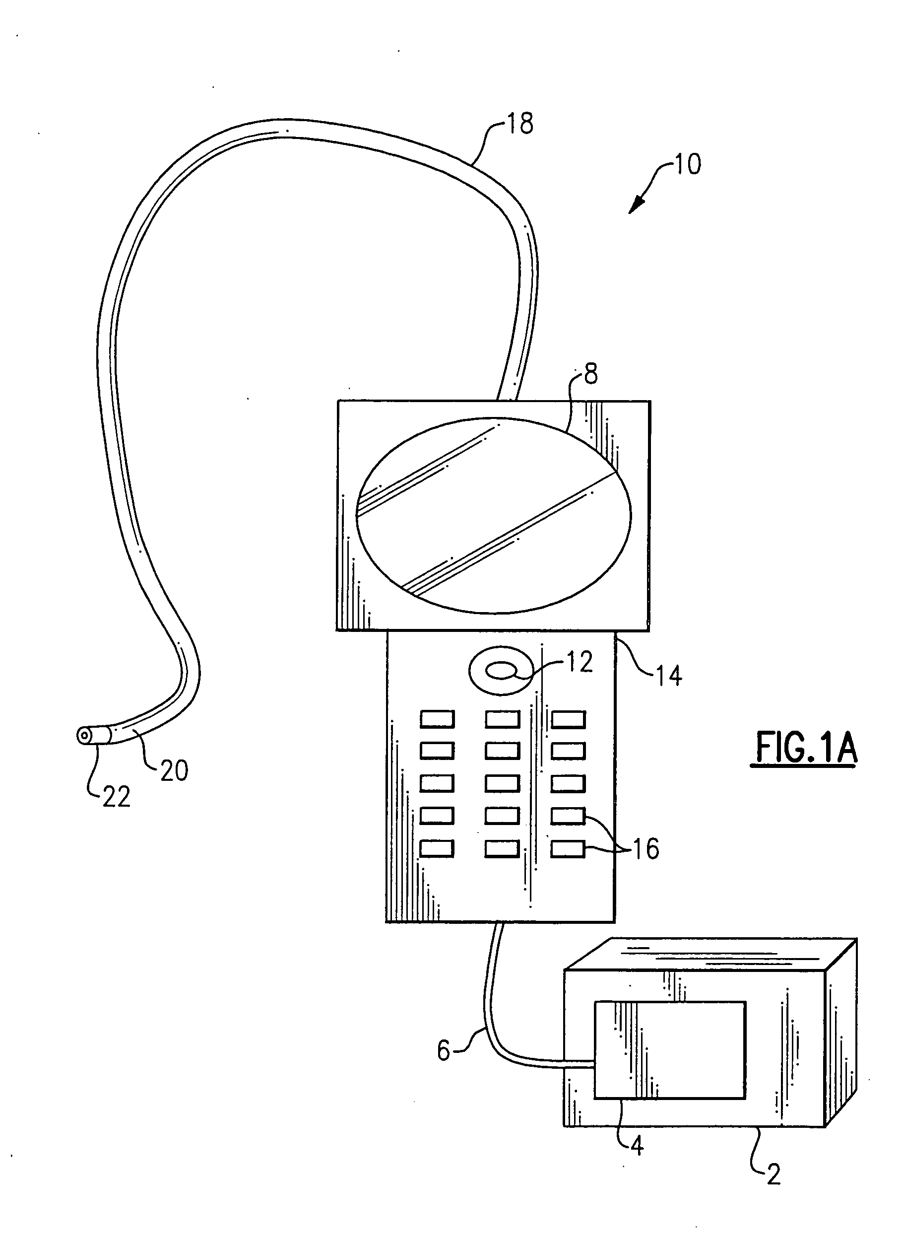
[0026] Referring to FIG. 1A, a typical remote viewing device 10 (a boroscope in the illustrative embodiment) according to the invention is illustrated, such as is sold by Everest VIT® of Flanders, N.J. Such a device could include, as shown in the illustrative embodiment, a portable shipping / operating case 2, which includes a power supply 4 for the device and a light source, such as a metal ...


PUM


Abstract

The present invention features a remote viewing device that is capable of improving its operation by removing slack in its control cables and / or by increasing the range of motion of its viewing head. In one embodiment, the method for improving the operation involves removing at least a portion of the slack in at least one control cable attached to a servo motor. The removal of at least a portion of the slack includes changing the position of a servo motor relative to a flexible tube termination block until a specified tension is encountered in at least one of the control cables. The method further includes determining first and second servo control signal values corresponding to no angular deflection and a specified deflection in a viewing head.

Description

CROSS-REFERENCE TO RELATED APPLICATIONS [0001] This application claims priority to and is a continuation-in-part of co-pending U.S. patent application Ser. No. 10 / 768,761 entitled Remote Video Inspection System, filed Jan. 29, 2004, which application is incorporated herein by reference in its entirety.FIELD OF THE INVENTION [0002] The invention relates generally to a system and method for improving the operation of a remote viewing device. More particularly the invention relates to changing the calibration settings of the remote viewing device's articulation servos to remove slack in the control cables and / or increase the range of motion of the viewing head. BACKGROUND [0003] Borescopes, endoscopes, fiberscopes and the like (herein after generally referred to as remote viewing devices) are widely used to provide visual inspection of physically difficult to reach or inhospitable environments. The movement of remote viewing devices is frequently controlled by articulation servos that ...

Claims


Application Information

Patent Timeline
Patent Type & Authority Applications(United States)
IPC IPC(8): A61B1/05G02B23/24
CPCA61B1/05G02B23/2469G02B23/24
Inventor LIA, RAYMOND A.SCOTT, JOSHUA L.
Owner GE INSPECTION TECH LP
Why Eureka
Try Eureka