
Orientable Tactical Light

Inactive Publication Date: 2013-08-22
BRINZEY GEORGE WALTER HULAK
View PDF4 Cites 6 Cited by
  • Summary
  • Abstract
  • Description
  • Claims
  • Application Information

AI Technical Summary

Benefits of technology

The present invention is for a tactical light that has visual diversionary features. It can move around in the environment outside of the housing and create unstable areas of shadow and light to keep the user's attention away from it. Additionally, the invention has a sensor that can illuminate specific areas. The sensor can produce multiple sensory effects and is supported by a movable assembly that has a different center of gravity than the housing. This technology can be used in tactical situations to provide temporary visual cues or distraction for the user.

Problems solved by technology

It is believed that resulting unstable areas of shadow and light act to distract and divert attention away from the user of the tactical light.
In other words, a device configured to provide sound pressure levels that are distracting, attention getting, and it is believed, in some cases painful.

Method used


Image

  • Orientable Tactical Light
  • Orientable Tactical Light
  • Orientable Tactical Light

Examples


Embodiment Construction

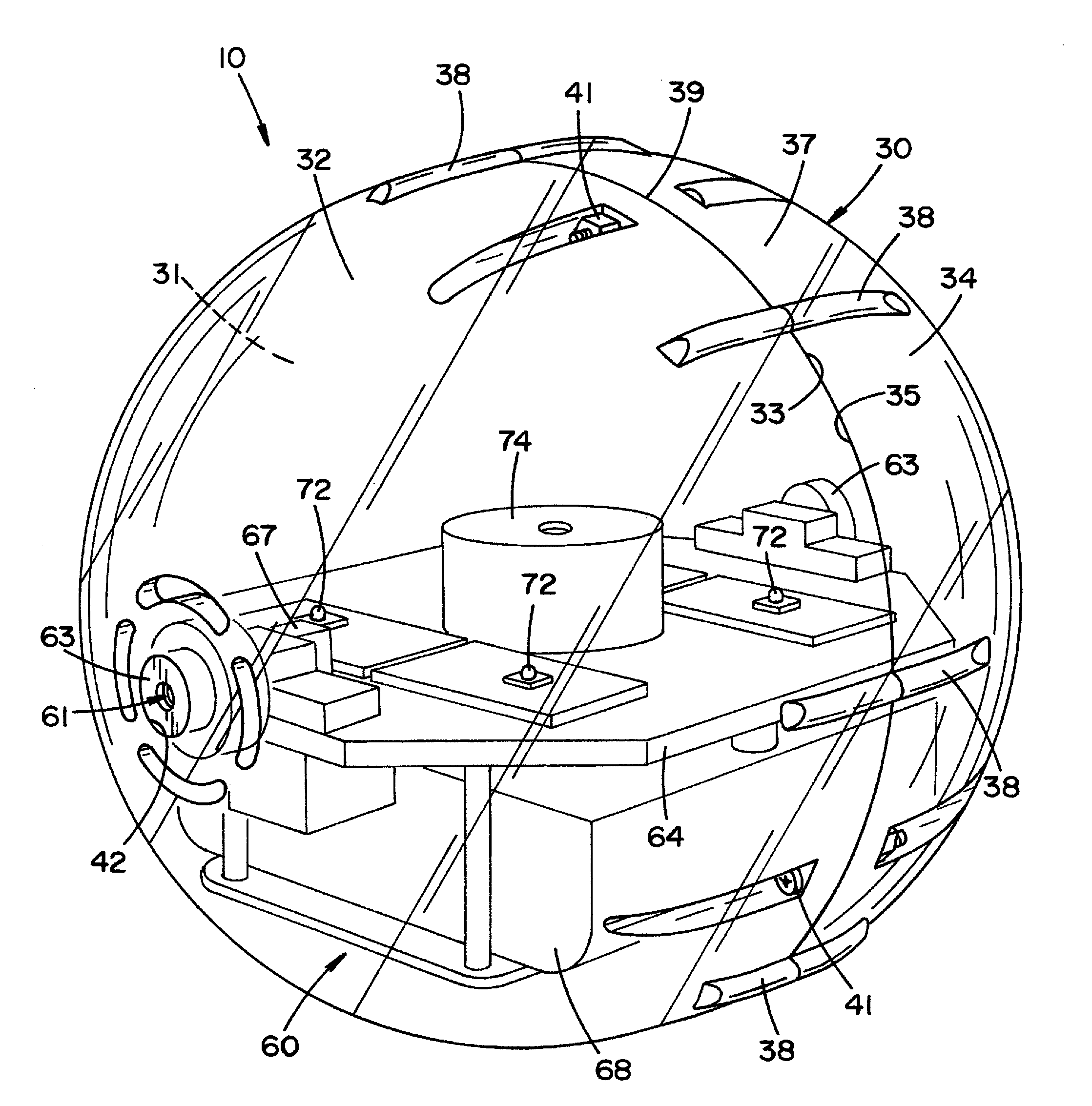
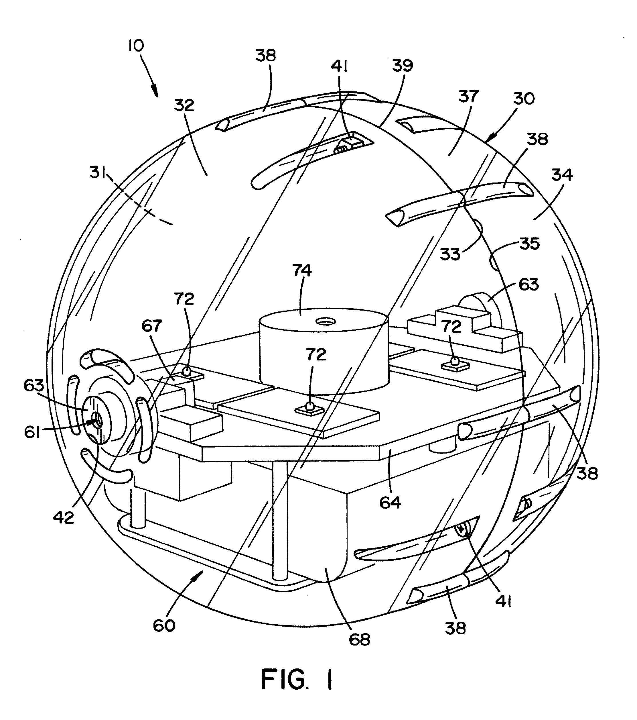
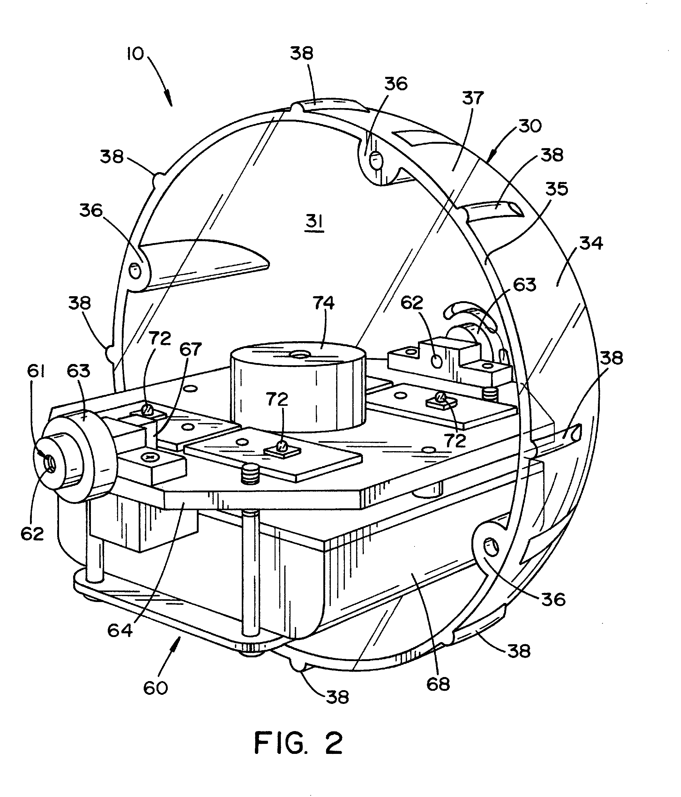
[0036]Embodiments of the present invention are directed to a tactical light 10 in which a propelled device is provided that can emit light in predetermined orientation relative to its center of gravity when light 10 is at rest and when light 10 is in motion. In this regard tactical light 10 can be rolled, tossed, otherwise launched with relative precision toward a predetermined location such that a predetermined area or areas are illuminated. Tactical light 10 is configured to come to rest on a surface such as a floor 14 as shown in FIGS. 3 and 4 or a grate 16, such as an expanded metal decking, as shown in FIG. 5.

[0037]Referring to FIGS. 1, 2, 7, and 8; in accordance with an embodiment of the invention, a tactical light includes a housing 30 having a substantially circular cross section. Housing 30 defines an interior space 31 that is configured to receive an effects assembly 60. Housing 30 includes a first shell 32 and a second shell 34. First shell section 32 and second shell sec...


PUM


Abstract

The present invention provides a tactical light configured such that it can be propelled toward a predetermined location. The tactical light includes a housing that defines an interior space. An effects assembly is configured to be positioned within the interior space defined by the housing. The effects assembly is rotatably connected to the housing by a rotary connector. The effects assembly is configured such that it has a center of gravity that is offset from an axis defined by the rotary connectors. In this regard, a light source positioned on the effects assembly is configured to illuminate a predetermined area relative to the effects assembly and its center of gravity and independent of the position of the surface of the housing relative to effects assembly.

Description

FIELD OF THE INVENTION[0001]The invention relates generally to lighting and specifically to a light emitting device, such as a tactical light, that is configured to return to a predetermined orientation after being thrown or rolled.BACKGROUND OF THE INVENTION[0002]Tactical lights are used by persons or groups such as military and police to provide illumination and distractions in areas where they are entering. Conventional tactical lights are configured to be tossed into a room away from the user. One purpose of a tactical light is to provide illumination of an area without disclosing the location of the user of the tactical light. In contrast, a conventional hand held flash light identifies the location of the user. Conventional tactical lights can be configured such that they generate a beam of light that is directed away from a support surface. In this regard, some conventional tactical lights are weighted such that they are self-righting. As a result, light can be emitted upward...

Claims


Application Information

Patent Timeline
IPC IPC(8): F21V15/01
CPCF41H13/0087F21V15/01F42B12/42
Inventor BRINZEY, GEORGE WALTER HULAK
Owner BRINZEY GEORGE WALTER HULAK
Learn More