Channel quality report processes, circuits and systems

a channel quality and circuit technology, applied in the field of electronic circuits, can solve problems such as interference and noise, undesired increase of system processing delays and power dissipation, and affect the monitoring of receivers

Active Publication Date: 2009-06-18
TEXAS INSTR INC
View PDF15 Cites 199 Cited by
  • Summary
  • Abstract
  • Description
  • Claims
  • Application Information

AI Technical Summary

Benefits of technology

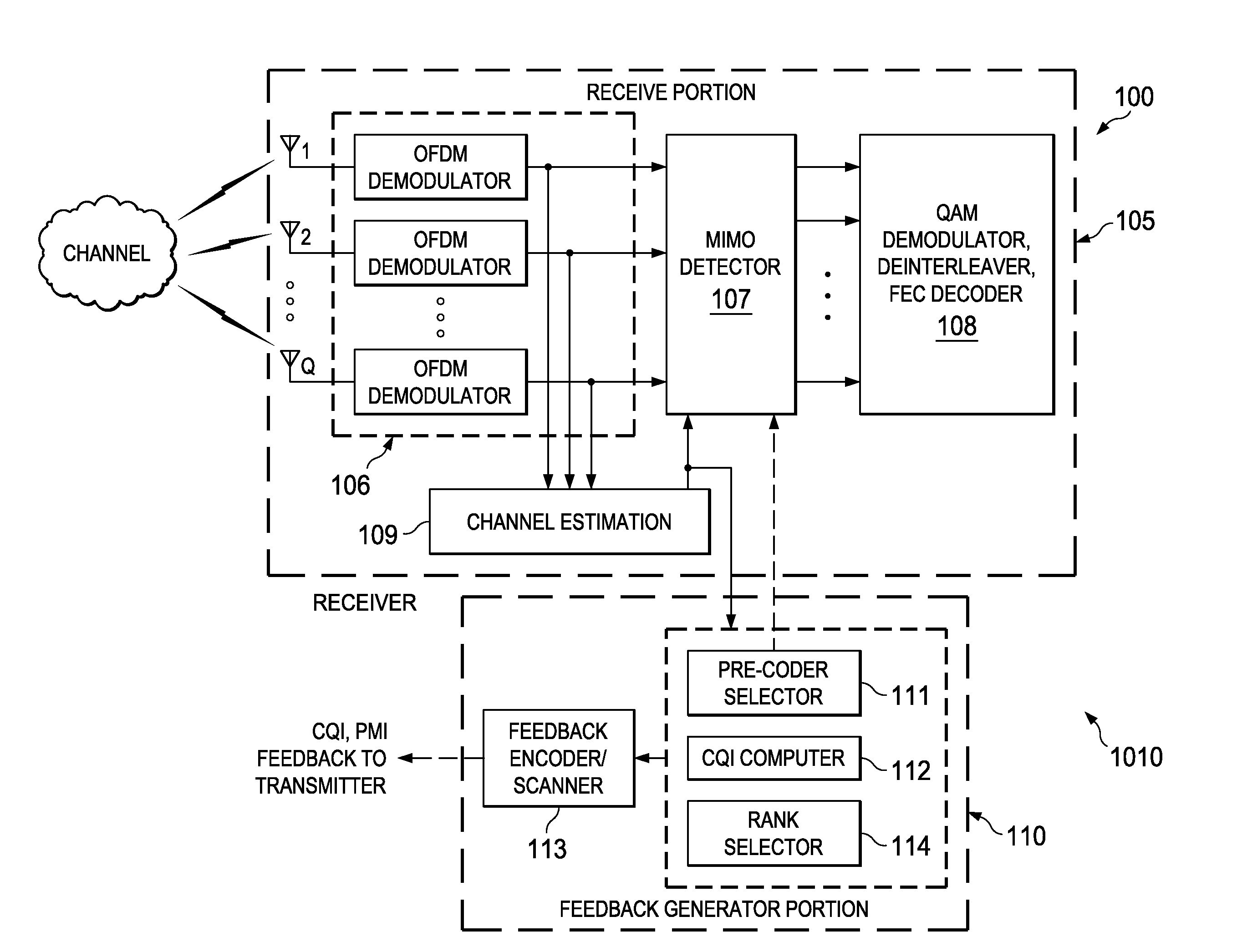
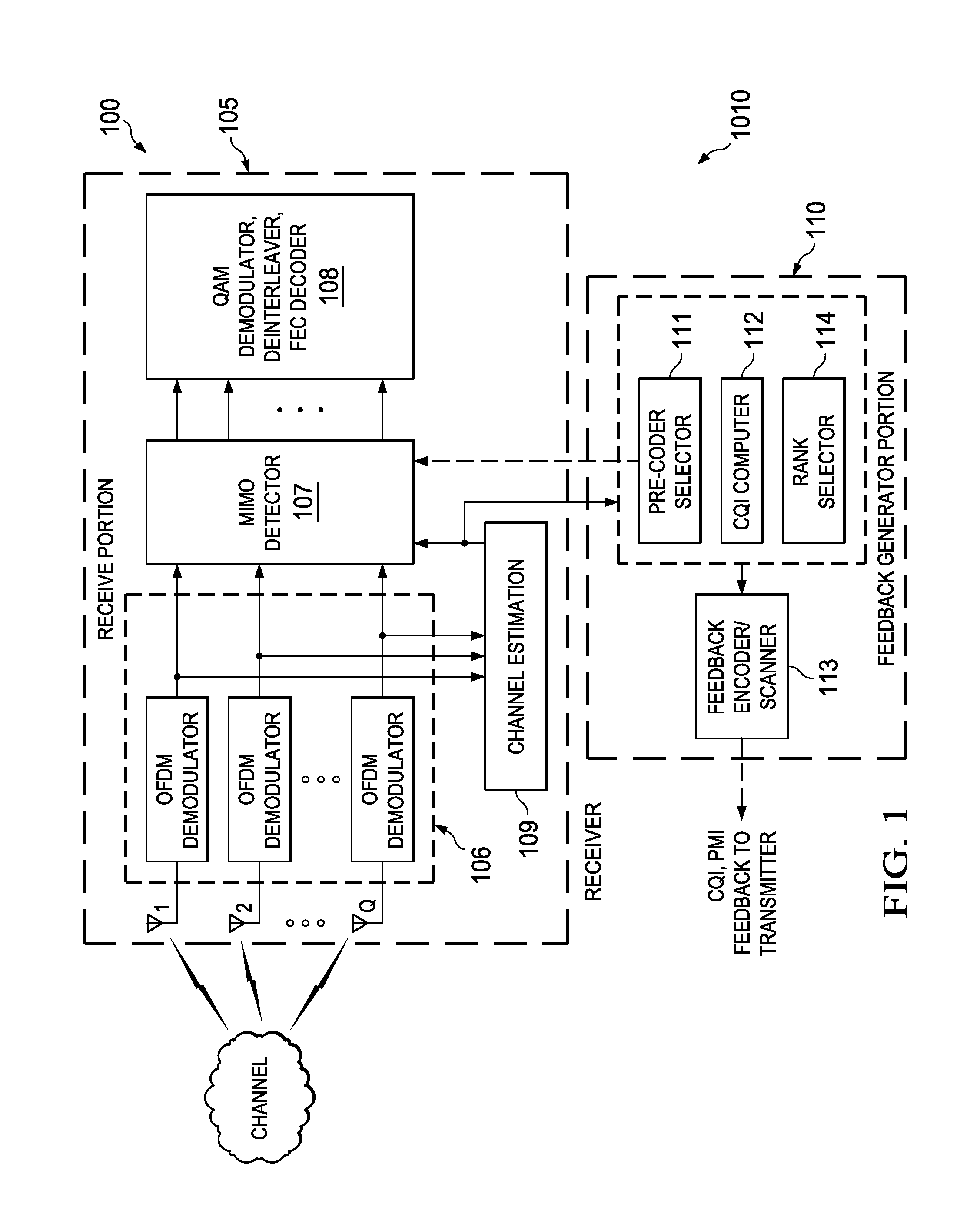
[0015]A form of the invention involves an electronic device that includes a first circuit operable to generate at least a first and a second channel quality indicator (CQI) vector associated with a plurality of subbands for each of at least first and second spatial codewords respectively and generate a first and a second reference CQI for the first and second spatial codewords, and operable to generate a first and a second differential subbands CQI vector for each spatial codeword and generate a differential between the second reference CQI and the first reference CQI, and further operable to form a CQI report derived from the first and the second differential subbands CQI vector for each spatial codeword as well as the differential between the second reference CQI and the first reference CQI; and a second circuit operable to initiate transmission of a signal communicating the CQI report.

Problems solved by technology

Base station eNB transmits reference signals or pilot signals to UE, which generates a channel estimate based on the reference signal, has impacted by interference and noise.
A high level of operational overhead and uplink bandwidth is believed to have hitherto been involved when each of many UEs deliver feedback about many subbands to eNB.
This can undesirably increase system processing delays and dissipation of power and energy which is of particular concern in mobile handset forms of UE.

Method used


Image

  • Channel quality report processes, circuits and systems
  • Channel quality report processes, circuits and systems
  • Channel quality report processes, circuits and systems

Examples


first embodiment

[0213]Uplink feedback 3670 is provided in any of a variety of embodiments related to FIG. 41 and described next. In a first embodiment, a CQI report vector is expressed as (SV, uF1, sF1, uΔr, sDr). In words, the CQI report vector has subband vector SV, the FIG. 21 mean / median / wideband collective CQI sF1 for the selected subbands for codeword CW1 and the FIG. 21 mean / median / wideband collective CQI uF1 for the unselected subbands for codeword CW1. The CQI report also includes the spatial CQI differences sDr between collective CQI sFr for the selected subbands relative to sF1 for codeword CW1. The CQI report further has the spatial CQI differences uΔr relative to CQI uF1 for the unselected subbands for codeword CW1. This is called vertical CQI reporting herein because the spatial CQI differences can be listed in columns vertically in TABLE 2. When spatial CQIs are quite similar in magnitude across code words r, and vertical CQI reporting delivers compression because both the spatial CQ...

third embodiment

[0215]In a third embodiment related to FIG. 41, a CQI report vector is expressed as (SV, sF1, sDr, −suDr), see also TABLE 4. In words, the CQI report vector has subband vector SV, the FIG. 21 mean / median / wideband collective CQI sF1 for the selected subbands for codeword CW1. (uF1 need not be explicitly reported.) The CQI report also includes the spatial CQI differences sDr for other spatial codewords relative to CQI sF1 for the selected subbands for codeword CW1. A reverse-horizontal CQI report usDr=−suDr=uFr−sFr delivers CQI differences in a given row for each codeword, r=1,2, . . . R.

TABLE 4BEST-m CQI REPORTING (“REVERSE-HORIZONTAL”)UnselectedSelectedSub-bandsSub-bandsCW1−suD1sF1CW2, etc.−suDrsDr

fourth embodiment

[0216]In a fourth embodiment category related to FIG. 41, any of the first three embodiments are subjected to joint quantization in step 3640. The CQI report vector has the form (SV, uF1, sF1, Ju, Js, R) for vertical reporting, and the form (SV, uF1, Ju, Jsu, R) or (SV, sF1, Js, Jus, R) for horizontal reporting. In the latter case, Jsu signifies a codebook index resulting from joint quantization of the horizontal difference vector suDr. Alternatively, Jus signifies a codebook index resulting from joint quantization of the horizontal difference vector −suDr. For substantially correlated difference vectors of either the vertical or horizontal or other type, joint quantization can offer useful compression.

[0217]In FIG. 41, base station eNB operations commence with eNB configuration BEGIN 3705 and configure subsets of subbands for each UEi in a step 3710. Operations continue via eNB Main BEGIN 3715 to a step 3720 that uses the feedback from each given UE to retrieve delta vectors from a...


PUM


Abstract

An electronic device includes a first circuit (111) operable to generate at least a first and a second channel quality indicator (CQI) vector associated with a plurality of subbands for each of at least first and second spatial codewords respectively and generate a first and a second reference CQI for the first and second spatial codewords, and operable to generate a first and a second differential subbands CQI vector for each spatial codeword and generate a differential between the second reference CQI and the first reference CQI, and further operable to form a CQI report derived from the first and the second differential subbands CQI vector for each spatial codeword as well as the differential between the second reference CQI and the first reference CQI; and a second circuit (113) operable to initiate transmission of a signal communicating the CQI report. Other electronic devices, processes and systems are also disclosed.

Description

CROSS-REFERENCES TO RELATED APPLICATIONS[0001]This application claims the benefit under 35 U.S.C. 119(e) of U.S. Provisional Application No. 61 / 013380 (TI-65716PS) entitled “CQI Feedback for MIMO-OFDMA Systems” filed on Dec. 13, 2007, and which is incorporated herein by reference in its entirety.[0002]This application claims the benefit under 35 U.S.C. 119(e) of U.S. Provisional Application No. 61 / 019802 (TI-65716PS1) entitled “CQI Feedback for MIMO-OFDMA Systems (update)” filed on Jan. 8, 2008, and which is incorporated herein by reference in its entirety.[0003]This application claims the benefit under 35 U.S.C. 120 of U.S. patent application “Precoding Matrix Feedback Processes, Circuits and Systems,” Ser. No. 12 / 188,767 (TI-65218) filed Aug. 8, 2008, and which is incorporated herein by reference in its entirety.[0004]U.S. Patent Application Publication 2008-0013610 “CQI Feedback For MIMO Deployments” of Jan. 17, 2008, and corresponding U.S. patent application Ser. No. 11 / 759,221 ...

Claims


Application Information

Patent Timeline
Patent Type & Authority Applications(United States)
IPC IPC(8): H04L27/28
CPCH04L1/0026H04L1/0029H04L5/0023H04L25/0228H04B17/24H04L2025/03808H04L5/0048H04L5/0057H04L25/03343H04B7/0639
Inventor CHEN, RUNHUAONGGOSANUSI, EKO N.
Owner TEXAS INSTR INC
Why Eureka
Try Eureka