Optical Fiber Combiner and Method of Manufacturing Thereof

a fiber laser and optical fiber technology, applied in the field of fiber lasers and fiber lasers, can solve the problems of reducing the brightness of the light source, reducing the efficiency of the optical output power offered by a single fiber laser operating in the so-called single mode fashion, and limiting the beam quality essentially diffraction,

Inactive Publication Date: 2009-06-18
CORELASE
View PDF5 Cites 37 Cited by
  • Summary
  • Abstract
  • Description
  • Claims
  • Application Information

AI Technical Summary

Benefits of technology

[0010]It is an aim of the invention to provide an improved method and dev

Problems solved by technology

However, the optical output power offered by a single fiber laser operating in the so called single mode fashion, i.e. with beam quality being essentially diffraction limited, is often limited to around 1 kW.
These designs are not well suitable for low-loss coupling of high beam quality laser light into a single fiber.
A problem associated with this kind of fusing is that the brightness is greatly reduced when light passes through the coupler.
The drawback of the first embodiment is that the fibers, and in particular thei

Method used


Image

  • Optical Fiber Combiner and Method of Manufacturing Thereof
  • Optical Fiber Combiner and Method of Manufacturing Thereof
  • Optical Fiber Combiner and Method of Manufacturing Thereof

Examples


Embodiment Construction

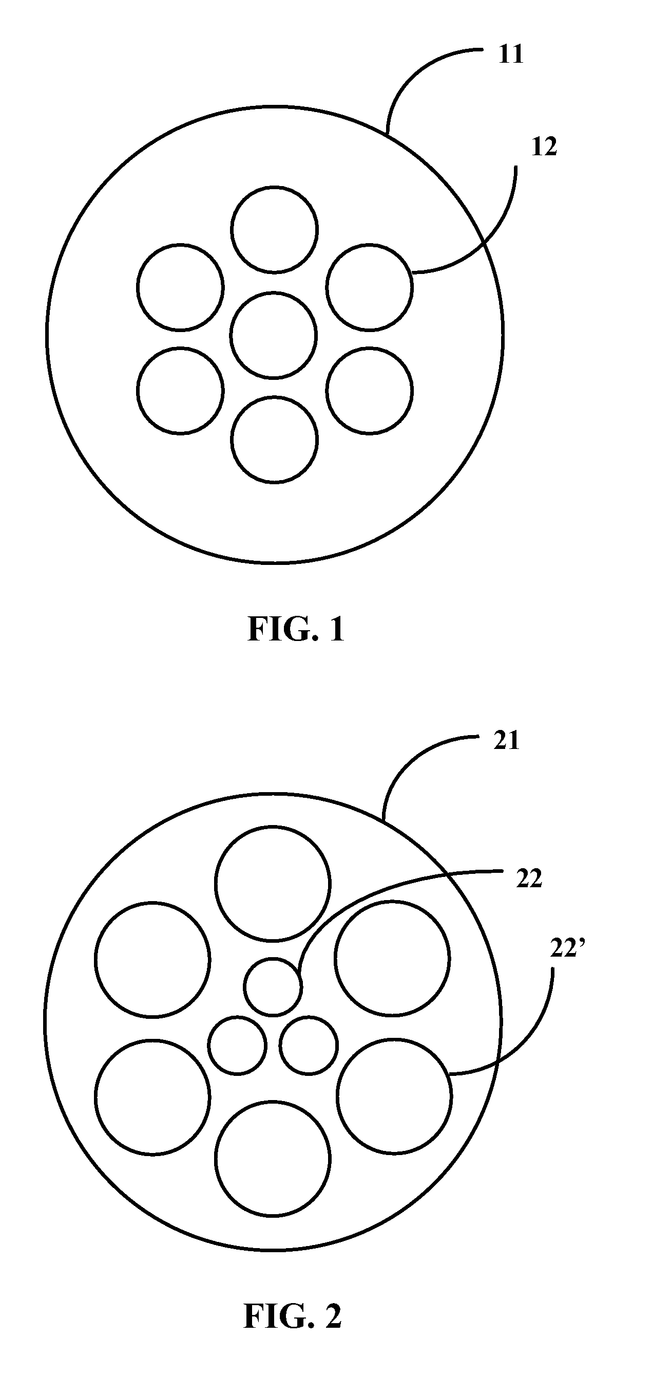
[0046]FIG. 1 shows a cross-section of a multi-bore capillary tube 11. The tube 11 is made of transparent glass material, preferably fused silica, fused quartz or some doped forms of them. The said materials are well matched with optical fibers in terms of thermal expansion coefficient. Since most common optical fibers are based on fused silica, it is a natural choice as the material for the said capillary tube. More than one bores or longitudinal holes 12 run through the tube in parallel with the longitudinal axis of the tube 11. In the example of FIG. 1 the seven bores are of equal diameter. In this case the capillary tube 11 may be used to combine seven lasers to a single output fiber.

[0047]FIG. 2 shows another example of a multi-bore capillary tube 21. As shown, bores 22 and 22′ of different diameters can be implemented into the same multi-bore capillary tube 21. In this example, the capillary tube 21 can be used to combine the optical radiation from two different types of input ...


PUM


Abstract

The invention relates to an optical fiber combiner and a method for the manufacture thereof. The combiner has a tapering support preform with a plurality of capillary bores, a plurality of input fibers including a core and a cladding around the core and being arranged in parallel in the capillary bores of a support preform, and an output fiber coupled to the tapered end of the support preform in optical connection with the input fibers. The cladding thickness to core thickness ratio of at least one of the input fibers is decreased at the region of the support preform. The invention provides an optically high quality fiber combiner.

Description

CROSS REFERENCE TO RELATED APPLICATIONS[0001]This application is a Continuation of co-pending International Application No. PCT / FI2007 / 050691, filed on Dec. 14, 2007, and for which priority is claimed under 35 U.S.C. §120, the entire contents of which are hereby incorporated by reference.BACKGROUND OF THE INVENTION[0002]1. Field of the Invention[0003]This invention is related to lasers and optical fibers. In particular, it is related to fiber-coupled lasers and fiber lasers. In the method according to the invention, optical radiation from multiple fibers is combined into a single fiber. The invention relates also to a fiber-optic component, hereinafter called a fiber combiner, used to combine optical radiation from several individual fibers and / or fiber-coupled lasers into a single output fiber or so called process fiber.[0004]2. Brief Discussion of the Related Art[0005]Fiber lasers have many attractive properties that make them suitable for various industrial applications. Such pro...

Claims


Application Information

Patent Timeline
IPC IPC(8): B29D11/00G02B6/26
CPCG02B6/2835G02B6/25
Inventor SALOKATVE, ARTO
Owner CORELASE
Why Eureka
Try Eureka