Plug connector

a plug and connector technology, applied in the direction of electrical equipment, connection, coupling device connection, etc., can solve the problem of not being able to achieve without destruction

Inactive Publication Date: 2009-06-25
ITT MFG ENTERPRISES LLC
View PDF4 Cites 8 Cited by
  • Summary
  • Abstract
  • Description
  • Claims
  • Application Information

AI Technical Summary

Benefits of technology

[0005]As a result of the measures according to the present invention, it is achieved that the insert, from the front end of the insulating member, i.e., without being impeded by the cables that have already been inserted into the insulating member, can be returned from

Problems solved by technology

In this context, although the insert is designed to be able to be moved once again with respect to the insulating member so that it is possible to return to the preliminary locking position in order to correct faulty placemen

Method used


Image

  • Plug connector
  • Plug connector
  • Plug connector

Examples


Embodiment Construction

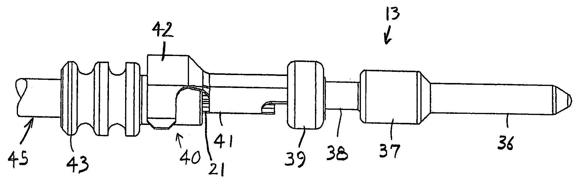
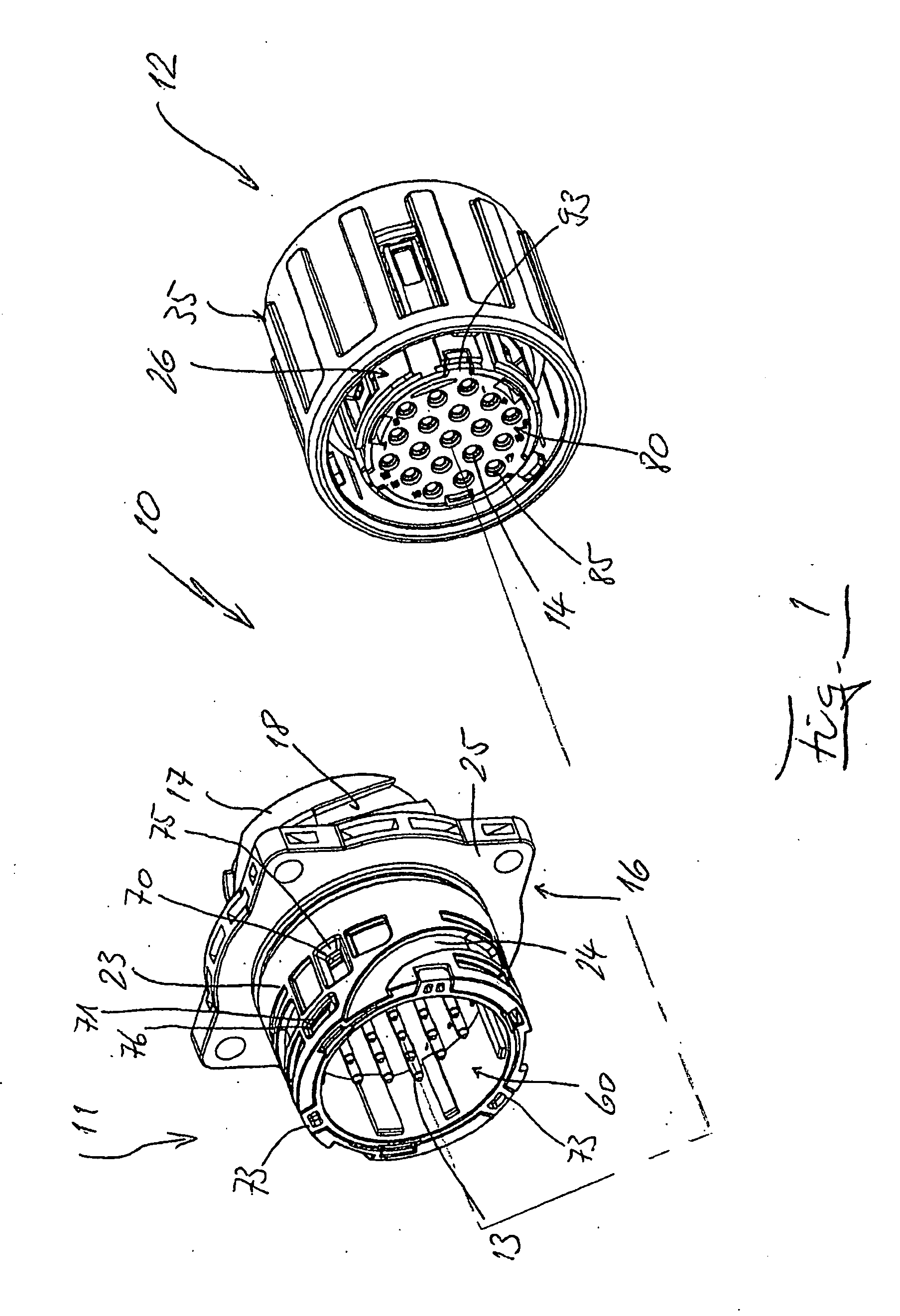
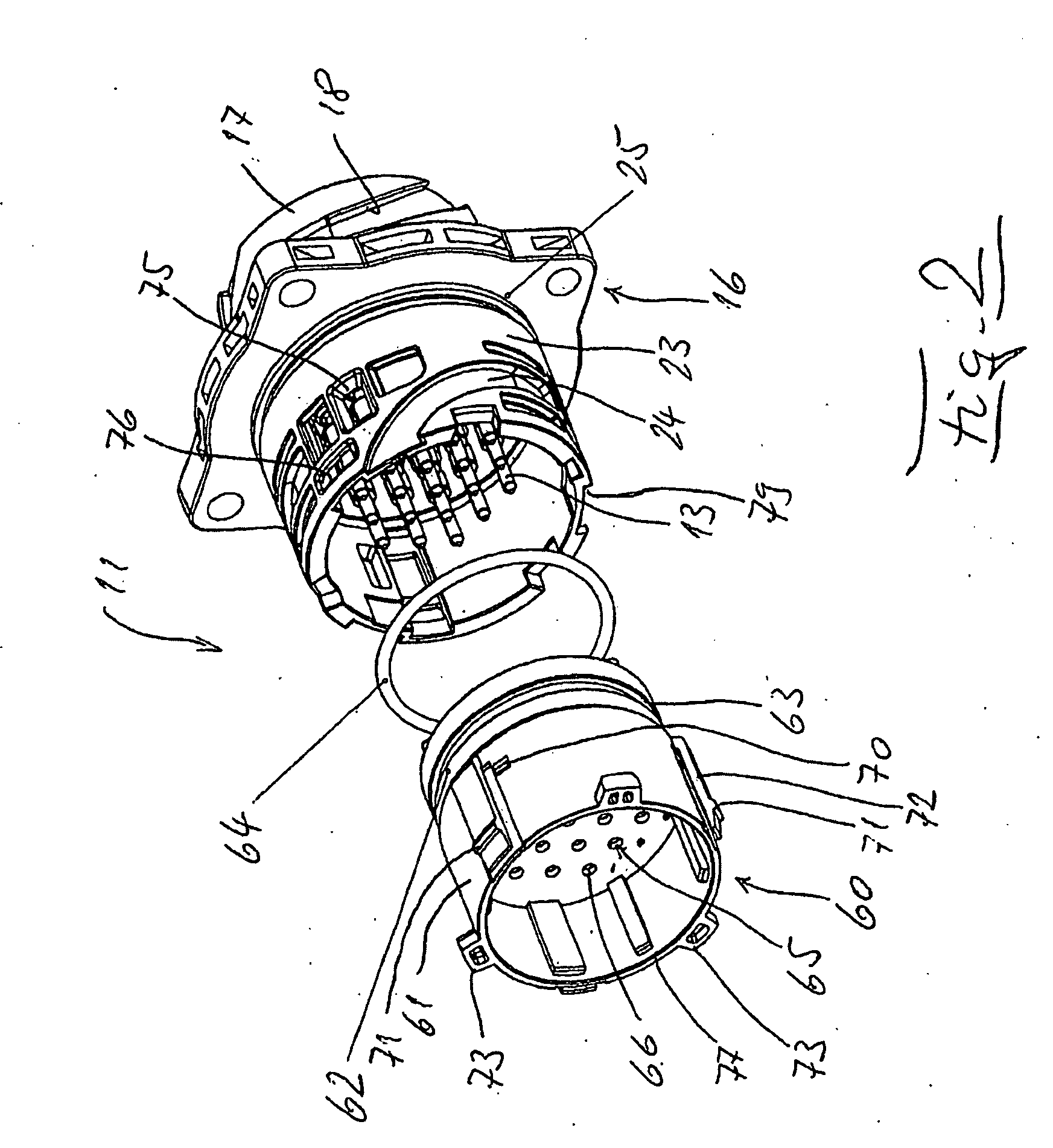
[0023]Plug connector device 10, as depicted in the drawing, is made up of a first plug connector 11 having male connector contacts 13 in accordance with FIG. 1A, and a second, or counter, plug connector 12 having female connector contacts 14 in accordance with FIG. 1B. Both plug connectors 11 and 12 in the exemplary embodiment are designed as having 19 poles (contacts), whereby connector contacts 13 and 14 are arranged so as to be uniformly distributed above and next to each other over a surface that is round when seen in a frontal view.

[0024]First plug connector 11 (FIGS. 1A and 2) contains an insulating housing 16, whose rear end 17 on the exterior periphery is provided with bayonet-type grooves 18 for a longitudinal sleeve of a bunched cable and on the interior side with a multiplicity of through boreholes 19 (FIGS. 4A and 4B), into which male connector contacts 13, each of which is provided with an individual cable core 21 (FIG. 3A), are inserted. Front end 23 (FIG. 1) of insula...


PUM


Abstract

A plug connector (11, 12, FIG. 1) has insulators (16,26) that hold male or female contacts (13, 14, FIG. 3) received in boreholes (19, 29, FIGS. 4A, 4B)). A rear insulator holds a male or female contact (13, 14), which receives cables (45, 55, FIG. 3). The boreholes (19, 29) form fingers (78, 98, FIGS. 4A and 6) that can be radially spread apart to detachably hold the connector contacts (13, 14) in a preliminary locking manner. The plug connector also has a front insert (60, 80) with a front borehole (65, 85) aligned with the rear boreholes (19, 29) and being able to be placed in a non-detachable preliminary locking position that makes possible the attachment of the connector contacts (13, 14) and in a final locking position that holds the connector contacts (13, 14) in a non-releasable fashion.

Description

CROSS-REFERENCE TO RELATED APPLICATION[0001]Applicant claims priority from German patent application no. 10 2007 063 207.1 filed Dec. 20, 2007.BACKGROUND OF THE INVENTION[0002]The present invention relates to a plug connector. By way of example, it is known from DE 10 2006 016 82 A1 to provide a plug connector with two latches for the connector contacts, whereby the first latch results in a non-detachable connection of the connector contacts with the insulating member, whereas the second latch functions to ensure that all the connector contacts are set in the prescribed, correct position via the first latch.[0003]In particular, in the case of plug connections that can be joined to a multiplicity of connector contacts, it is desirable that the customer himself see to the placement in the plug connectors of connector contacts that are already provided with cables. In this context, it seems to be necessary that said placement initially occur through a preliminary locking step, which in...

Claims


Application Information

Patent Timeline
IPC IPC(8): H01R13/627
CPCH01R13/432H01R13/625H01R13/5221H01R13/4367
Inventor SCHIMMELE-BRELL, TOBIASSCHREMMER, ANDREAS MICHAELSINGER, HELMUTWERDER, GERHARDWYDERKA, ANDREAS WOLFGANGTAXIS, GERALDSIGLE, EGON
Owner ITT MFG ENTERPRISES LLC
Why Eureka
Try Eureka