Reclining Device

a technology of reclining device and guide, which is applied in the field of reclining device, can solve the problems of locking gear pushing and deformation of fixed guides, and achieve the effects of reducing the number of components, reducing friction, and simplifying the structure of the devi

Active Publication Date: 2010-03-25
IMASEN ELECTRIC IND
View PDF6 Cites 7 Cited by
  • Summary
  • Abstract
  • Description
  • Claims
  • Application Information

AI Technical Summary

Benefits of technology

[0032]The reclining device can be provided with a pair of movable guides. Each of the movable guides can have a wedge-like shape the width of which gradually decreases from the outer end toward the inner end. Each of the movable guides can be disposed between the lock gear and the fixed guide. Each of the movable guides can be imparted with a force toward an inner direction of the base plate by a spring. So configured, each of the movable guides is sandwiched between the lock gear and the fixed guide 30. The fixed guide, the lock gear, and the movable guide are then maintained in close contact with one another with no gap between them. Consequently, mechanical play in the front and rear direction of the seat back can be reliably eliminated, and the lock gear and the movable guide can be reliably locked with and released from each other.
[0033]In some embodiments, each of the movable guides is arranged so that the sliding face near the lock gear is parallel to a movement direction of the lock gear. This can prevent the movable guide from catching against the lock gear. Mechanical play in a front and rear direction of the seat back can also be eliminated, and the movable guides can be reliably locked and unlocked.
[0034]The lock gears can be formed so that their width gradually decreases from their inner ends toward their outer ends. The sliding face of each of the lock gears near its fixed guide can be parallel to the lock gear's direction of movement. The lock gear is thereby formed with an inclined surface near the movable guide. The movable guide, which has a wedge-like shape, is disposed between the inclined surface and the fixed guide. The sliding faces are held in a close contact with each other, and the outer teeth of the lock gear engage with the inner teeth of the gear plate. The rotation of the gear plate is thereby locked, and the seat is thus not allowed to recline. To unlock the seat and allow it to recline, the center shaft is rotated to disengage the outer teeth of the lock gears from the inner teeth of the gear plate. The contact face between the lock gear and the movable guide is inclined with respect to a movement direction of the lock gear. When the lock gear is pulled in an inner direction, the lock gear and the movable guide can be separated with very little friction generated between them. The lock gear can thereby be pulled inward smoothly and without significantly pushing out the movable guide with the link plate, and the lock can thus be released. The reclining device can be constructed from only a few component parts.
[0035]In some embodiments the movable guides are attached to the respective ends of a torsion spring. The base plate will in that case not require any engagement portions for the spring, and the number of component parts can be reduced and the structure of the device simplified. This facilitates the assembly of the reclining device, which can reduce its cost of manufacture and enhance its durability.
[0036]In some embodiments, each of the two torsion springs is attached to a cam at one end of the spring and to one of the movable guides at the other. This configuration pulls the movable guides along a diagonal line. Inward forces are thereby imparted to the movable guides, with a rotational force imparted uniformly to the cam from two directions. The cam is thus not imparted with a force in an eccentric direction. The cam is rotated at the center of the base plate, because the pushing force of the cam 50 is applied uniformly to both of the lock gears. The outer teeth of the lock gears engage with the inner teeth of the gear plate, and locking is reliably achieved.
[0037]In some embodiments each of the movable guides will have outer teeth at the outer end of the guide. When an overload is applied to the reclining device during a vehicle collision or the like, a rotational load is transmitted from the gear plate to the lock gears. The lock gears then push the movable guides between the fixed guides. Each of the movable guides is formed with a width that gradually decreases from the outer end toward the inner end. Each of the movable guides is pushed outwardly along the base plate. The outer teeth at the outer end of the movable guides move toward the inner teeth of the gear plate and are engaged with them. The movable guides and the lock gears thereby prevent the gear plate from rotating. When an overload is applied to the reclining device during a vehicle collision or the like, the movable guides and the lock gears thereby prevent rotation of the gear plate, and unintended inclination of the seat back is prevented in the collision.

Problems solved by technology

Therefore, when an overload is applied to the reclining device upon a vehicle collision or the like, the lock gears will push and deform the fixed guides.

Method used


Image

  • Reclining Device
  • Reclining Device
  • Reclining Device

Examples


embodiment 1

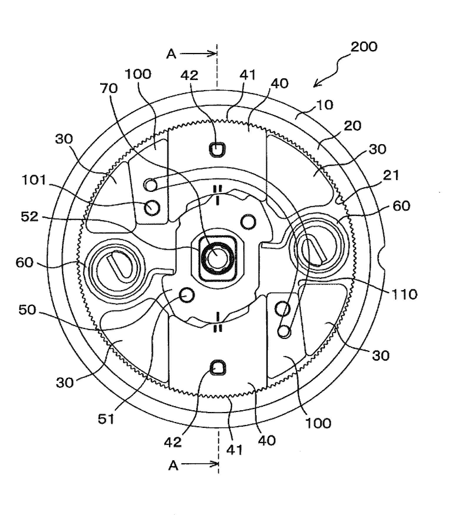
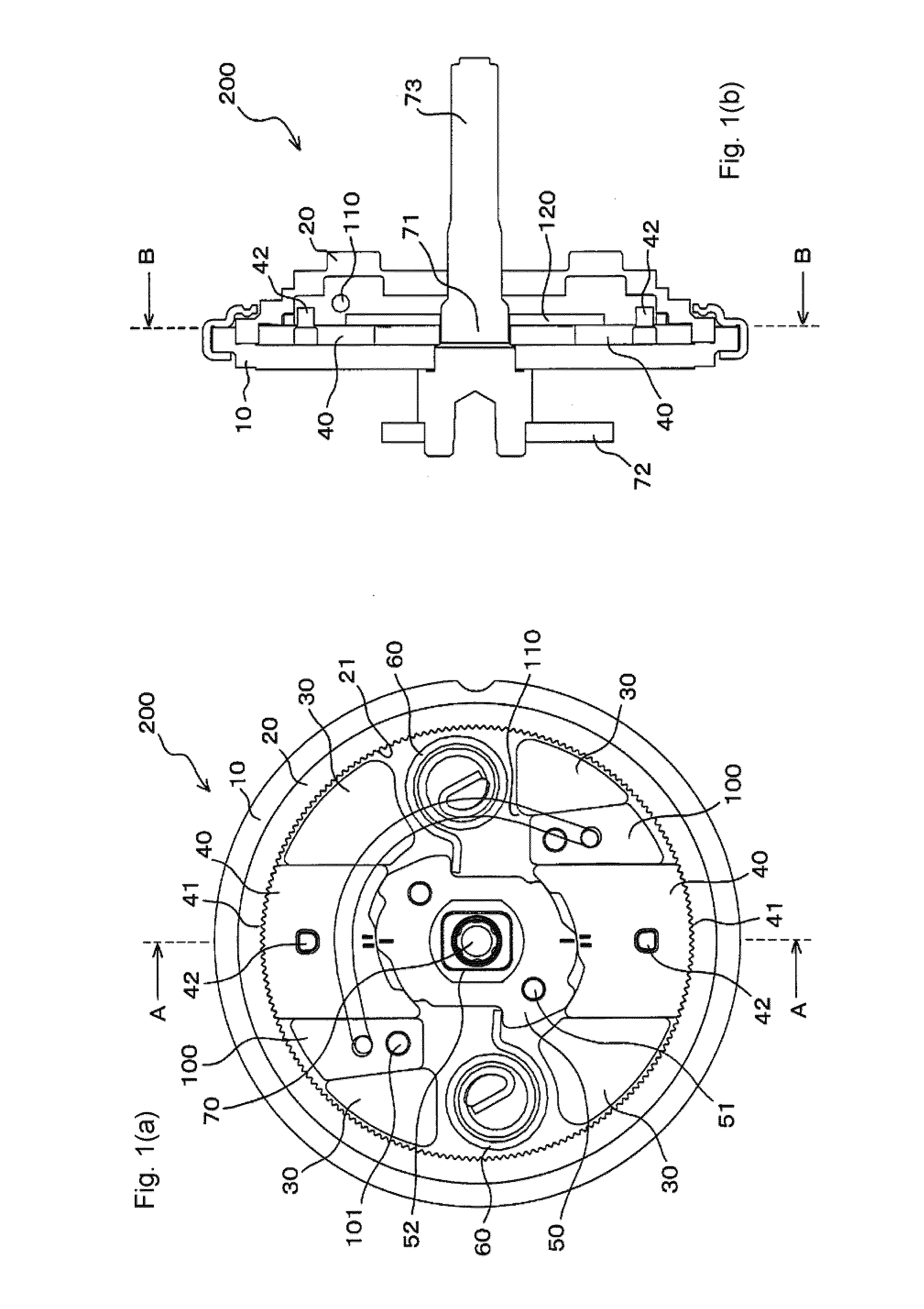
[0073]FIGS. 1(a), 1(b), 2, 3, and 4 illustrate a reclining device 200 according to a first embodiment. The reclining device 200 includes a base plate 10, a gear plate 20, fixed guides 30, lock gears 40, a cam 50, springs 60, a center shaft 70, movable guides 100, a spring 110, and a link plate 120. These components are described in more detail below.

[0074]The base plate 10 is a base of the reclining device 200. The base plate 10 is fixed to either of a seat cushion or a seat back of a vehicle seat. The base plate 10 has to be strong enough to support a load of the seat back and the weight of an occupant. Therefore, the base plate 10 is formed of steel plate and processed by press working or cutting. In the first embodiment, the base plate 10 is has a circular exterior shape formed by press working a steel plate. The base plate 10 is also formed with fixed guides 30. The fixed guides 30 are fixed to the seat cushion.

[0075]The gear plate 20 is assembled with the base plate 10 with the...

embodiment 2

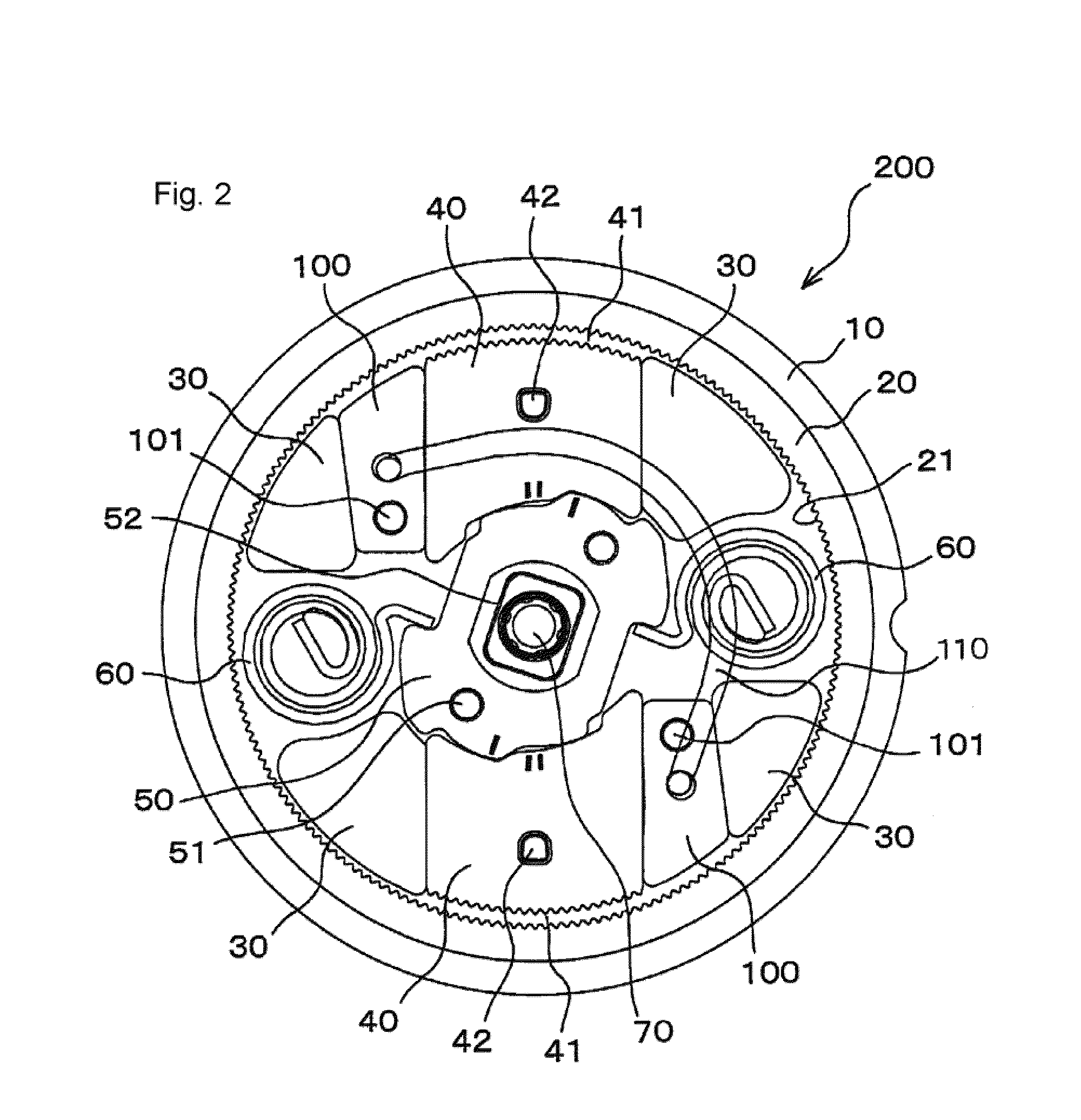
[0087]FIG. 5 illustrates a reclining device 200 according to a second embodiment. The reclining device 200 is the same as that of the first embodiment in many respects. Particular points of difference are described, but descriptions of similar features are omitted. In the second embodiment a vertical torsion spring 60 imparts a rotational force to the cam 50 as shown in FIG. 5. In this embodiment, the link plate 120 in particular is not shown for the convenience of description. The reclining device 200 may though include the link plate 120. In this second embodiment, the single torsion spring 60 imparts the rotational force to the cam 50. The reclining device 200 can be constructed of fewer component parts than those in the first embodiment.

embodiment 3

[0088]FIG. 6 illustrates a reclining device 200 according to a third embodiment. The reclining device 200 according to this embodiment is the same as the first embodiment in many respects. Points particularly different from those of the first embodiment are described here, but descriptions of identical features are omitted. In this third embodiment, a pair of torsion springs 110, ends of which are attached to the pair of movable guides 100, impart a rotational force to the cam 50 as shown in FIG. 6. Accordingly, the pair of torsion springs 110 is engaged with the cam 50 and the pair of the movable guides 100. The pair of torsion springs 110 is disposed on a diagonal line symmetrically with respect to the center shaft 70. The cam 50 is thereby imparted uniformly with a rotational force from two directions. Consequently, in this embodiment the cam 50 is prevented from being driven by a force in an eccentric direction. The cam 50 can thus be rotated around the center of the base plate ...


PUM


Abstract

A reclining device capable of eliminating mechanical play in a front-rear direction of a seat back is provided. Particularly, a reclining device reliably capable of locking and releasing is provided at an inexpensive cost. Movable guides are slidably disposed respectively between lock gears and a fixed guide. Each of the movable guides is formed in a shape that the width thereof gradually decreases from the outer end toward the inner end. In the sliding faces of the respective movable guides, a sliding face on the lock gear side is arranged to be parallel to a movement direction of the lock gear and the sliding face at the fixed guide side is inclined with respect to the sliding face at the side of the lock gear. Each of the movable guides engages with a spring and the spring imparts a force to the movable guides in an inner direction of a base plate.

Description

RELATED APPLICATIONS[0001]This application is a divisional of U.S. patent application Ser. No. 12 / 192,122 having a filing date of Aug. 15, 2008, having been published on Mar. 12, 2009 as Publication No.: 2009-0066137 A1, and now pending, which is a continuation of International Application PCT / JP2007 / 052816, with an international filing date of Feb. 16, 2007, now abandoned, which claims priority to Japanese Application JP2006-039639, having a filing date of Feb. 16, 2006, now pending, and Japanese Application JP2006-045011, having a filing date of Feb. 22, 2006, now pending, all of which are hereby incorporated herein by reference.TECHNICAL FIELD[0002]The present invention relates to a reclining device for vehicle seats, and more particularly to a reclining device that eliminates mechanical play in a front and rear direction of a seat back to prevent unintended inclination movement of the seat back upon a vehicle collision.BACKGROUND OF THE INVENTION[0003]Vehicle seats are often pro...

Claims


Application Information

Patent Timeline
Patent Type & Authority Applications(United States)
IPC IPC(8): B60N2/42A47C1/025B60N2/22
CPCB60N2205/20B60N2/2356B60N2/236A47C1/025B60N2/42
Inventor ISHIHARA, YOSHITAKAESAKI, TAKUTOHARA, KAZUYOSHI
Owner IMASEN ELECTRIC IND
Why Eureka
Try Eureka